Part 2 Using the meter...
https://www.fiero.nl/forum/Forum2/HTML/081601.htmlPart3
https://www.fiero.nl/forum/Forum2/HTML/082148.htmlNote: I plan on this being part 1 of a possible 3 part series.
Many have asked about meter use, guess I will put some of my old EE training to work and create one or our Fieros. If you have tips or see corrections please throw them out.
I'll start out with tips for buying a meter along with clarification of terms, and interpreting readings.
When it comes to electrical checks are you guessing where the problem is? What do you do n a no-start situation? What do you do when the starter solenoid just clicks? What do you do when the lights are dim at idle? How do you check a computer ground circuit problem? Do you replace parts because you heard someone else had a similar problem and hope it works for you?
When the first computer controlled system came about around 1980 many mechanics only had digital or analog meters. This was all there was unless you had access to manufacturers equipment.
Digital voltmeter cost vary from as low as $20 on up. The lower cost meters will buy you lots of good electrical measurements to test and analyze good and bad electrical circuits.
These meter applications and measurements will be slower than the more advanced ones however the results can be just as accurate, provided the user understands meter application and measurement principles.
If you have not yet purchased a volt meter, be certain to examine several makes so you'll get the model that's right for the job.
Displays: Look for large display digits, plainly marked knobs and test lead jacks.
Test leads: Look for test lead sturdiness equipped with screw-on alligator clip ends. After have this type you will understand why.
Sears offers a couple low cost meter that are fairly nice.
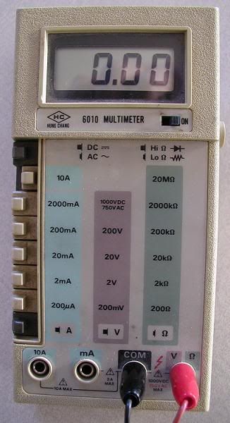
Here is my old trusty meter. Plan on getting a Sears one this year.

Meter Terms
Volts and Millivolts
When measuring voltage on computer controlled vehicles you must be fluent in converting volts to millivolts or vise versa.
Examples:
0.2volts is read as 2 tens of a volt.
0.02volt is two hundredths of a volt.
0.002 istwo thousandths of a volt.
Convert volts to millivolts by multiplying by 1000.
0.2volts x 1000 = 200 millivolts.
0.02volts is 20 millivolts.
0.002 volts is 2 millivolts.
Ohms and Kilohms or K ohms.
Reading resistance is just as important
2.5ohms is two point five ohms, a typical injector resistance.
300 ohms, a typical coolant sensor resistance on a hot engine.
3000 ohms or 3K, the average resistance for each foot of a new carbon core spark plug wire.
30,000 thirty thousand ohms or 30K.
For most auto applications consider that 30K ohms is the maximum acceptable resistance standard for any suppression core or carbon core spark plug wire. If over 30K ohms, replace it.
Now on most digital meters the display usually shows K ohms meaning thousandths of ohms.
Thus 3.146K on the display is 3146 ohms.
Amps and Milliamps.
Some typical examples for current flow.
3.0amps = 3 amperes. This is the approximate average current flow in an electronic ignition primary circuit.
3 ma = 3 milliamps or 0.003 amps. 3Ma is the approximate current flow in a generic coolant sensor circuit.
Volt Scales.
A digital voltmeter includes a function switch with a different absolute ranges.
What does that mean? The range you choose is sets the maximum voltage you can measure on that scale.
For example.
0-200 mv is zero to 200 millivolts.
0-2 volts.
0-20 volts.
0-200 volts.
In a TPS (Throttle Position Sensor) circuit the signal voltage might be 0.52 volts at closed throttle. However if we didn't know this, we would start with the 0-20 scale reading 0.52 volts.
When using a fixed scale, start with the highest scale first. If the reading is very low, select the next lower scale for better accuracy.
If the scale you select is lower than the expected voltage, the digital meter will display OL or a 1.
This means the voltage has exceeded the selected voltage range. If this happens just switch to the next higher range.
If you happen to have an auto-ranging digital meter the meter will select the correct scale range for the circuit being measured. However they can sometime take a couple seconds to switch ranges.
Bar Graphs.
Bar graphs are handy to look for glitches. The bar graph increases or decreases almost as fast as the sensor signal voltage changes. A bar graph can be hand for checking a TPS sensor but not necessary.
They can also be used on an O2 sensor to see it vary from 0.2 to 0.8 volts. Many bar graph meters can also be set for average or instantaneous reading. On average you can see what the average value of the O2 might be running which would relate to lean or rich.
OK the end of Part 1. Part 2 will be voltmeter hookups and resistance measurements. Stay tuned in the next day or so.
[This message has been edited by Dodgerunner (edited 04-22-2007).]


 Guessing you meant: