Pennock's Fiero Forum
  Technical Discussion & Questions - Archive
  Low buck 88 Front Coilovers with adjustable ride height

T H I S   I S   A N   A R C H I V E D   T O P I C
  

Email This Page to Someone! | Printable Version


Low buck 88 Front Coilovers with adjustable ride height by fieroguru
Started on: 01-21-2012 09:54 AM
Replies: 11
Last post by: 2002z28ssconv on 02-29-2012 07:34 PM
fieroguru
Member
Posts: 12330
From: Champaign, IL
Registered: Aug 2003


Feedback score:    (45)
Leave feedback


Total ratings: 259
Rate this member

Report this Post01-21-2012 09:54 AM Click Here to See the Profile for fieroguruSend a Private Message to fieroguruDirect Link to This Post
Ever since this thread I have wanted to give this project a try with a slightly different spin.
https://www.fiero.nl/forum/A...120111-2-091747.html

A couple of key take aways from the project above, the 375 rate was a bit much (I would prefer 275 to 300) and adjustment to the ride height was difficult to make due to the lack of space between the top side of the a-arm and the spring pocket on the 88 front crossmember.

My goals are to get a 300 lb/in front spring rate for a good compromise between handling and road harshness, but with the ability to raise/lower the car with minimal effort. Around home I would keep it fairly low due to the smooth roads, but when on a road trip (like the HRPT) and going to areas with suspect roads, I could raise it back up to avoid bottoming out on the nasty roads.

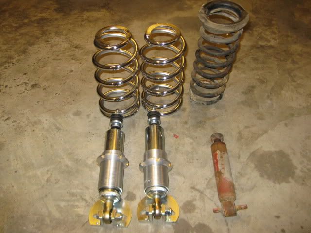
ProShocks sells a similar kit C200/GM300 that can be had for $325.25 shipped from Autoplicity.com so that is what I started with. This kit is used to convert GM products to front coil overs with tapered springs and this kit comes with a 300 lb/in spring rate. It is designed to just slide in place of the stock spring and includes a mounting bracket intended to sit on the bottom spring perch and spread the load similar to how the stock spring would do.

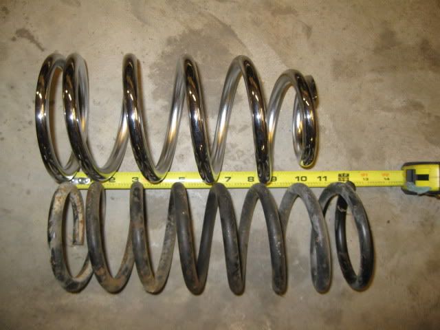
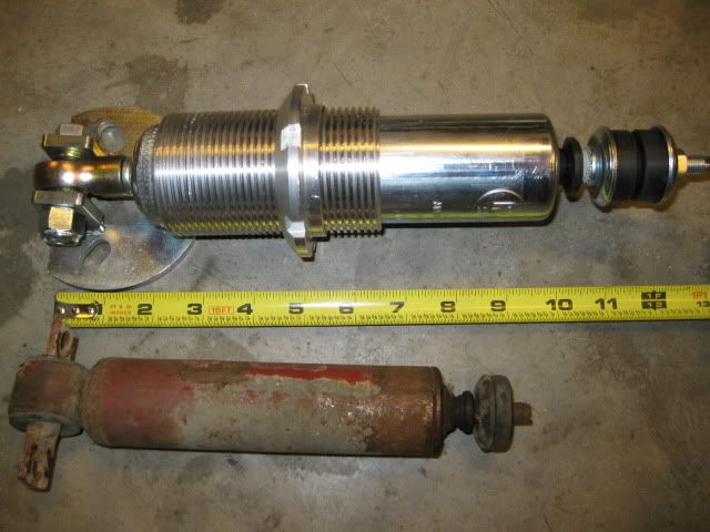
The upside to this kit is the price, the downside to this kit is the springs are 10" in length and the shock is a couple inches too long. So some cutting/welding will be required.
The kit along side a stock 88 formula spring and shock:


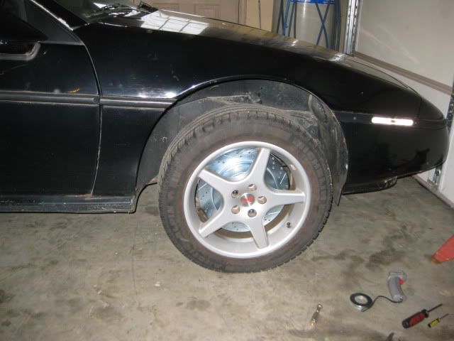
Just for grins, I put the spring in to check the ride height... It is about 1/2" higher than a stock 88 (which is too high)... 4x4 anyone!


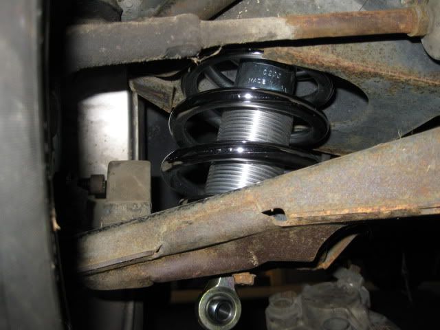
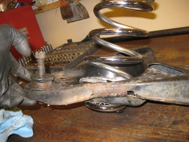
Notice there is lots of room between the rod end and the wheel and floor... lots of room for the shock/spring to be mounted lower. The spring needs to actually pass through the a-arm to get to an acceptable ride height, and by doing so the the adjuster sleeve will be below the a-arm as well and could improve access to it for adjustment. By lowering the mounting point at the a-arm, I can fix the spring length issue and the shock length issue with 1 modification to the lower a-arm.

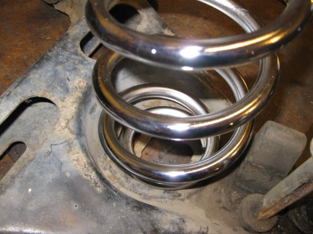
From this pic you can see that the spring is smaller in diameter than the spring pocket on the a-arm, so it should have ample clearance to pass through.


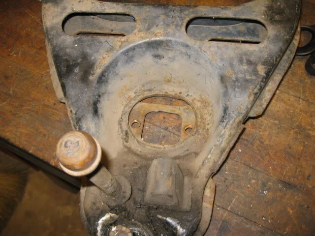
Time to start hacking up an 88 lower a-arm... good thing I have spares!

[This message has been edited by fieroguru (edited 01-21-2012).]

IP: Logged
PFF
System Bot
qwikgta
Member
Posts: 4669
From: Virginia Beach, VA
Registered: Jan 2001


Feedback score:    (21)
Leave feedback


Total ratings: 84
Rate this member

Report this Post01-21-2012 10:04 AM Click Here to See the Profile for qwikgtaSend a Private Message to qwikgtaDirect Link to This Post
you had me at 88

Rob
IP: Logged
fieroguru
Member
Posts: 12330
From: Champaign, IL
Registered: Aug 2003


Feedback score:    (45)
Leave feedback


Total ratings: 259
Rate this member

Report this Post01-21-2012 01:45 PM Click Here to See the Profile for fieroguruSend a Private Message to fieroguruDirect Link to This Post
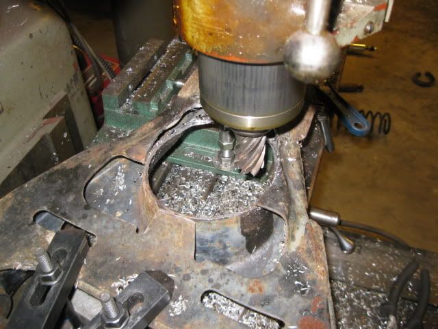
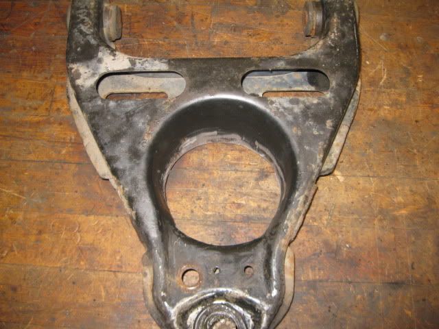
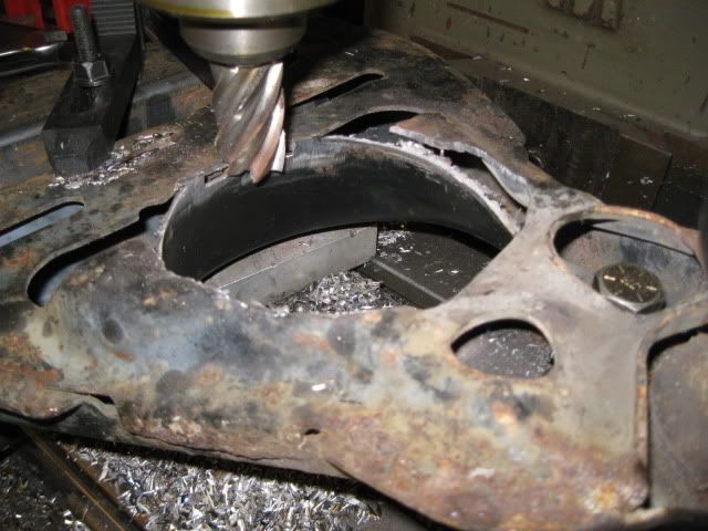
I thought I could cut out the bottom of the spring pocket with the 4 1/2" hole saw, but it wasn't working like I wanted it, so I just bolted the A-arm down to the mill with the bottom shock mount surface level and started cutting it away. I used the outer edge of the pocket material as a guide for cutting the hole.


First pass wasn't quite large enough:


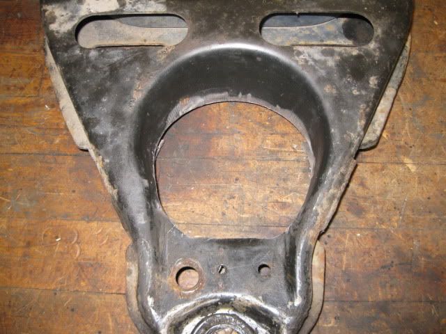
So back in the mill for a 2nd pass:


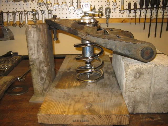
I am probably going to do a 3rd pass to increase the current clearance, but it was good enough to start the mockup to see how this all could come together. Here is a crude mockup with the original shock mount leveled to the bench and the sping/shock/shock bracket in place:


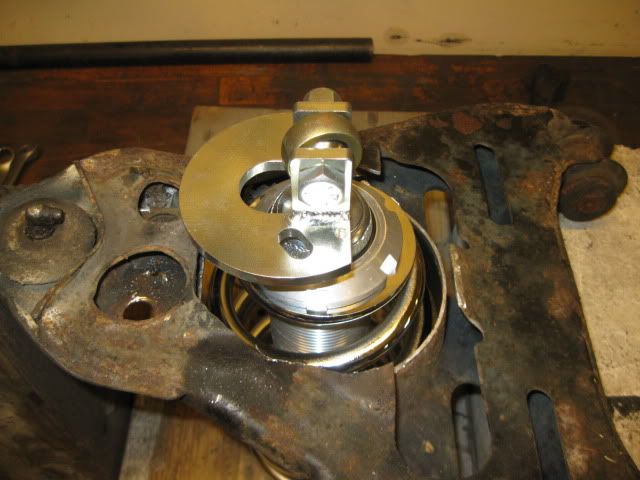
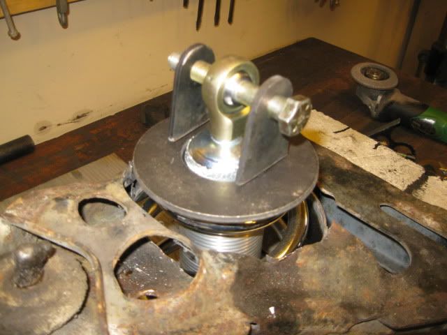
Never liked the bracket supplied with this kit, so I had already ordered some really LARGE washers (they are about $4.50 each, so not too expensive) figuring I would be making a new lower shock mount. First up is the largest one (I know the tabs need to be shorter so the shock can articulate in the hole... but the tabs were just sitting there). The tabs are $9 for a pack of 5, so they are fairly cheap as well:


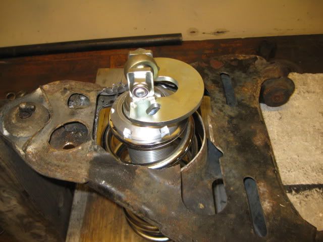
Here is a smaller washer for comparison:


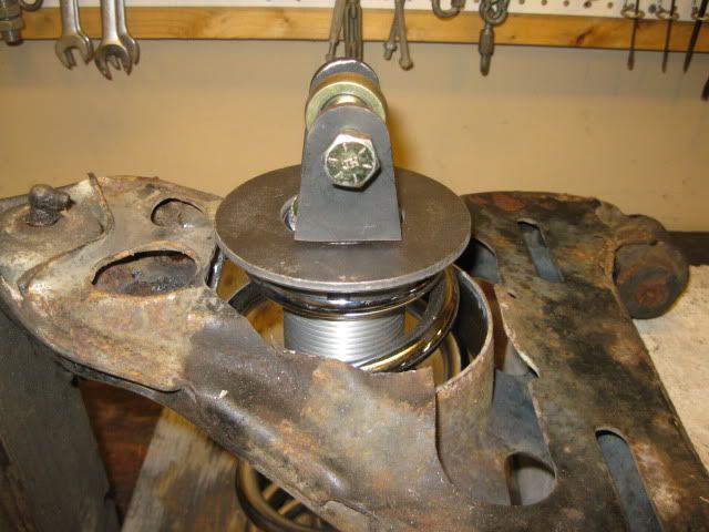
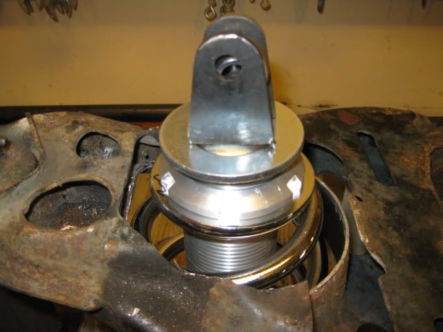
Not really feeling the small washer, so the monster one will probably get used. Then it will be a matter of closing up the gap and restoring the strength to the lower A-arm. Here is the first contender:


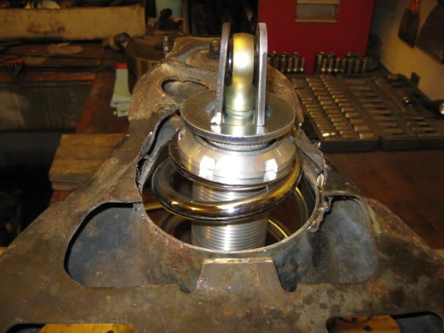
Here is the 2nd contender:


I am leaning towards doing something similar to the 2nd one, but with a little bit different path. Girls are back and it is nap/quiet time, so I will do some more playing around with card board. I will probably spend a couple of days "just thinking" about the lower attachment before I commit to a design.

[This message has been edited by fieroguru (edited 01-21-2012).]

IP: Logged
Bloozberry
Member
Posts: 7760
From:
Registered: Jan 2009


Feedback score: N/A
Leave feedback


Total ratings: 311
Rate this member

Report this Post01-21-2012 02:41 PM Click Here to See the Profile for BloozberrySend a Private Message to BloozberryDirect Link to This Post
Interesting idea, although I'll be interested in how "low-buck" it really is after the machine work and fabrication is done!

I thought I'd mention a potential weakness I found in the stock '88 lower control arms since you're making modifications anyway. The cross sectional area of the control arm "rails" that run down either side of the spring pocket is very small. While drafting up my build thread drawings I noticed that four different '88 lower control arms were curved like the one in the drawing below. It's easy to see when you take a straight edge on the top flat part of the arm and run it from the bushing area to the ball joint. I doubt they were made this way but I have a hard time understanding what loads would bend them in that direction. Regardless, it's interesting to note that the bend starts at the weakest area of the arm, and in line with where all the loads are carried (the spring seat). Maybe I'm reading more into this than I should.

IP: Logged
carbon
Member
Posts: 4767
From: Eagan, MN
Registered: Apr 2004


Feedback score: (2)
Leave feedback


Total ratings: 132
Rate this member

Report this Post01-21-2012 03:38 PM Click Here to See the Profile for carbonSend a Private Message to carbonDirect Link to This Post
(<-- No material strength analysis skills...)

Pre-loaded like a semi truck flatbed? Against the spring pressure...
IP: Logged
fieroguru
Member
Posts: 12330
From: Champaign, IL
Registered: Aug 2003


Feedback score:    (45)
Leave feedback


Total ratings: 259
Rate this member

Report this Post01-21-2012 04:55 PM Click Here to See the Profile for fieroguruSend a Private Message to fieroguruDirect Link to This Post
If the arm was bent the other way, then it would suggest that it was bent due to the spring load. However, with it being the other direction my guess is the curvature was either intentional, or a byproduct of all the localized welding at the nose of the control arm.

If I add the style 2 gussets, then it will better reinforce the arm from any potential bending forces.
IP: Logged
fieroguru
Member
Posts: 12330
From: Champaign, IL
Registered: Aug 2003


Feedback score:    (45)
Leave feedback


Total ratings: 259
Rate this member

Report this Post01-22-2012 10:44 AM Click Here to See the Profile for fieroguruSend a Private Message to fieroguruDirect Link to This Post
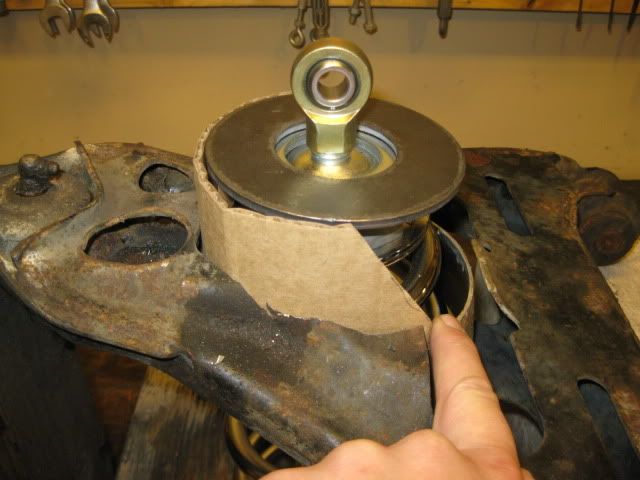
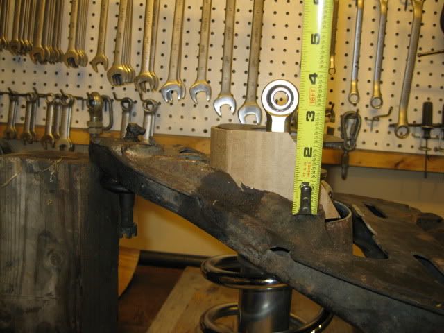
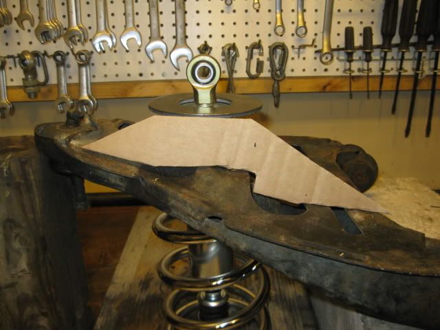
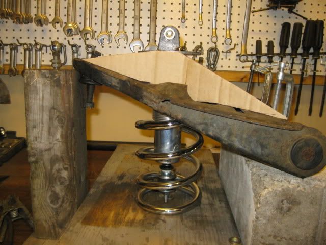
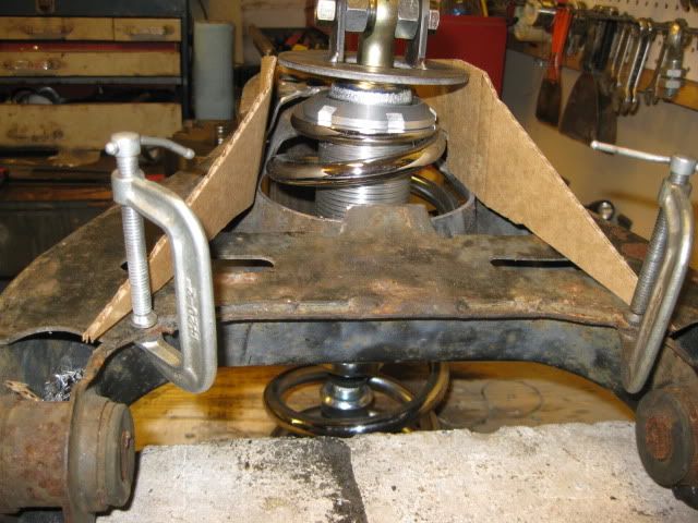
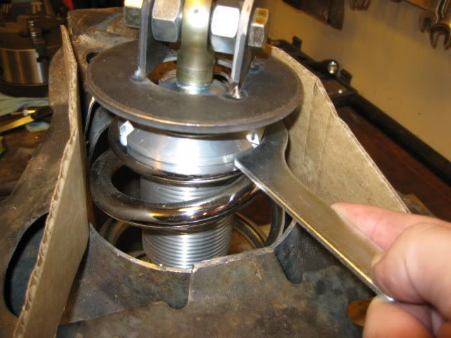
I went ahead and cut down the inner spring area level with the bottom/back side of the control arm (or about 1/2" more). Then I made up some better fitting card board gussets to check for fit and to ensure the spanner wrench could work between the two gussets:


There is plenty of room for the spanner wrench to rotate the sleeve 1 tooth at a time, so this setup will allow adjustment from the underside the a-arm.

[This message has been edited by fieroguru (edited 01-22-2012).]

IP: Logged
Raydar
Member
Posts: 40962
From: Carrollton GA. Out in the... country.
Registered: Oct 1999


Feedback score:    (13)
Leave feedback


Total ratings: 460
Rate this member

Report this Post01-22-2012 12:55 PM Click Here to See the Profile for RaydarSend a Private Message to RaydarDirect Link to This Post
What kind of ground clearance is that going to provide?
IP: Logged
fieroguru
Member
Posts: 12330
From: Champaign, IL
Registered: Aug 2003


Feedback score:    (45)
Leave feedback


Total ratings: 259
Rate this member

Report this Post01-22-2012 01:27 PM Click Here to See the Profile for fieroguruSend a Private Message to fieroguruDirect Link to This Post
 
quote
Originally posted by Raydar:

What kind of ground clearance is that going to provide?


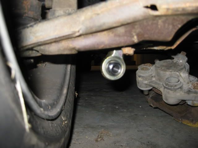
I forgot to show this pic. The rod end has several inches before it hits the ground and was already protruding about 1 1/2". The new setup is 2" lower or protruding by 3.5 inches. There should still be about 3" between the rod end and the pavement. With it being so close to the wheel, I doubt it would be any issue.

IP: Logged
qwikgta
Member
Posts: 4669
From: Virginia Beach, VA
Registered: Jan 2001


Feedback score:    (21)
Leave feedback


Total ratings: 84
Rate this member

Report this Post02-29-2012 01:51 PM Click Here to See the Profile for qwikgtaSend a Private Message to qwikgtaDirect Link to This Post
 
quote
Originally posted by Bloozberry:
While drafting up my build thread drawings I noticed that four different '88 lower control arms were curved like the one in the drawing below. It's easy to see when you take a straight edge on the top flat part of the arm and run it from the bushing area to the ball joint. I doubt they were made this way but I have a hard time understanding what loads would bend them in that direction.


I have a set of 88 lowers that are also bent, but my thought was that someone at sometime had used the shock tube (bottom) as a place for a floor jack or a larger hydrolic jack. Mine were very bent but just the spring perch area was effected. So muc so, that the spring would not sit in them without a degree of "lean" making it difficult to get the damn things into the spring pocket up top.

Oh yea, and "Bump for an update"

Rob
IP: Logged
qwikgta
Member
Posts: 4669
From: Virginia Beach, VA
Registered: Jan 2001


Feedback score:    (21)
Leave feedback


Total ratings: 84
Rate this member

Report this Post02-29-2012 02:45 PM Click Here to See the Profile for qwikgtaSend a Private Message to qwikgtaDirect Link to This Post

qwikgta

4669 posts
Member since Jan 2001
EDIT - After typing all this, had I just opened this link https://www.fiero.nl/forum/A...120111-2-091747.html , id have gotten all my answers. Nevermind. - EDIT


Guru,
As you know we have been PM’ing on other suspension and brake issues for the 88’s. I had some questions about this setup.

http://www.qa1.net/qa1_moto...ngle-adjustable.html

On this site you can see that QA1 offers a lot of different size shocks, both selectable in compressed/extended height, with a recommended spring size too. These shocks can be modified to switch the top mounting “loop” to a nut/bolt setup like we use on our cars. Here is the link for that part. http://www.qa1.net/qa1_moto...conversion-kits.html

In your setup, you have to cut a lot of the bottom out of the LCA, and a lot of it's going to be hanging down. I know you have measured it and have room but I’d be a little concerned with the shock being that low. I would think that you could modify the LCA like you are by welding in the lower shock piece but not have to move it so low if you purchased the correct QA1 shock from the website above. I know they are expensive for R&D purpose, but if you were able to create a kit that was kind of a morph between the WCF Koni relocate kit (For 88 only) http://www.westcoastfiero.c...ero_koni_shocks.html and the HT Motorsports Coil Over kit (for 88) http://arrautmotorsports.co...pension-information/ you may be able to bridge the gap in price. $500 for the WCF kit, $1150 for the HT kit (with QA1 upgrade).

I would think that using the stock Fiero LCA, modified with a lower plate to support the coil over shock, and the correct QA1 coil over would come in around $600-700 bucks. The R&D on the correct parts would be pricy upfront unless the research done before the purchase worked this out. Plus, the R&D parts could also be sold to defray cost.

Some questions are:
Which QA1 shock will be the correct size to fit between the LCA and the shock tower?
Will the stock shock upper location need to be modified for the QA1 coil over top? If so, what is needed and can this be done without significant modification? (HT motorsports page says it does not need to be modified, I also called Richard about this, and he states no modifications are needed)
What would be needed to be done to the LCA to mount the QA1 lower shock mount? Would the average owner have the ability to do this? (cut and bolt similar to WCF kit or cut and weld in kit)
After all this is done, would the setup provide adequate spring rate, and suspension travel, and offer the ability to lower the suspension enough to be “worth the effort”?

I know for you it's easy, you have master fab skills. The rest of us need a bolt in / easy kit.

Looking forward to your thoughts on this.

Rob

[This message has been edited by qwikgta (edited 02-29-2012).]

IP: Logged
PFF
System Bot
2002z28ssconv
Member
Posts: 1436
From: Orlando, FL
Registered: Jun 2005


Feedback score:    (27)
Leave feedback


Total ratings: 51
Rate this member

Report this Post02-29-2012 07:34 PM Click Here to See the Profile for 2002z28ssconvClick Here to visit 2002z28ssconv's HomePageSend a Private Message to 2002z28ssconvDirect Link to This Post
I still plan to put the other ones I made into the upcoming Fiero project. I think the primary solution to my whole problem would be to get shorter springs from the company I listed in my thread. Either that or have the QA1 springs (that I already have) shortened. Then I would be able to lower the car like I wanted to.

I also have designed a tubular lower control arm that will drop the spring perch lower than the stock location. That would solve the whole problem of modifying the stock A arm and I could keep the same QA1 springs. I recently had to have some welding done on our bush hog and found a guy with a machine shop that likes to take on small welding projects. I think I'll see what he can do with my control arm design.

Nice to see an idea of mine get someone else thinking even though my attempt fizzled out.
IP: Logged


All times are ET (US)

T H I S   I S   A N   A R C H I V E D   T O P I C
  

Contact Us | Back To Main Page

Advertizing on PFF | Fiero Parts Vendors
PFF Merchandise | Fiero Gallery
Real-Time Chat | Fiero Related Auctions on eBay


Copyright (c) 1999, C. Pennock