
 
     |
| F40 6 Speed 3.09 Final Drive Upgrade (Page 1/8) |

|
fieroguru
|
AUG 20, 05:22 PM
|
|
The G6 version of the F40 (MT2) comes with a 3.55 final drive and a 3.77 1st gear, which provides a sump pulling 1st gear and isn't ideal with higher powered engine swaps. The low first gear is one of the criticisms for the F40, and FWD manual transmissions in general.
The F40 continues to live on in several Buick, Opel, Vauxhall applications and has versions with the following final drive ratios: 3.091, 3.348, 3.545, 3.762, 3.895, 3.909, and 4.176 (information courtesy of FieroWannaBe), but several of these final drives are only available over sees.
The 3.091 (F84) is an optional final drive in the F40 (MYJ) paired with the a20dth diesel engine in the Insignias (possibly other applications). Since it is optional, it takes some double checking to verify it has the proper final drive. I picked up my diesel F40 on eBay.co.uk and had it shipped to the US via TNT and Fedex.
Here are the gear ratios of both the G6 and the MYJ and the hybrid with the G6 gears 1-6 and the 3.09 final drive.
code:
Trans	Final Drive	1st	2nd	3rd	4th	5th	6th
G6	3.55		3.77	2.04	1.32	0.95	0.76	0.62
MYJ	3.09		4.17	2.13	1.32	0.95	0.76	0.62

Hybrid	3.09		3.77	2.04	1.32	0.95	0.76	0.62
Here is the 3.09 F40 that came from the UK.
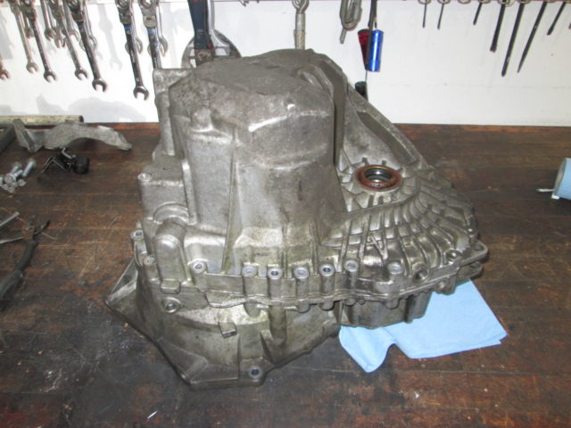
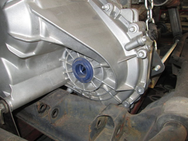
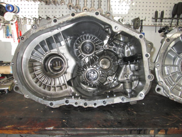
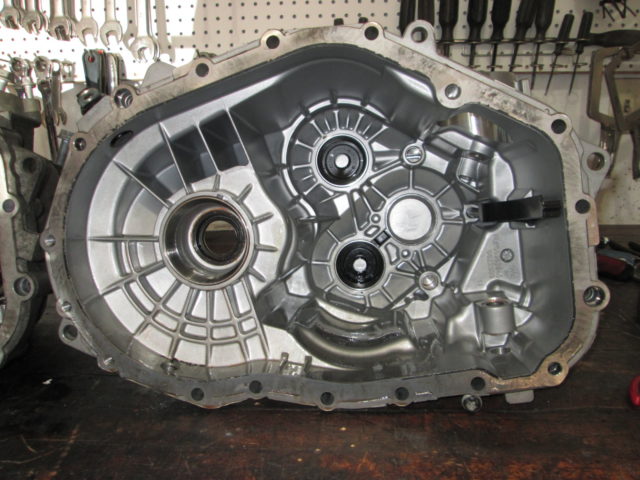
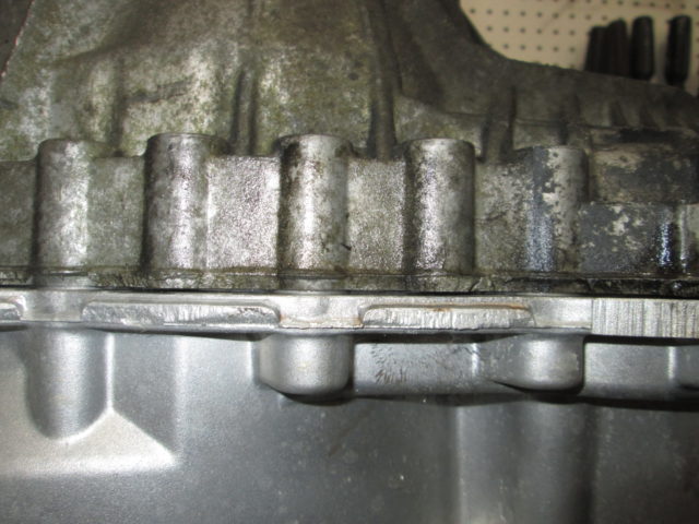
The pictures below will show some of the differences between the 3.09 transmission (dirty) and the G6 F40 (clean).
High level the differences are:
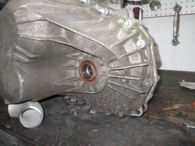
Bellhousing bolt pattern is different (and the MYJ bellhousing is deeper)
Transmission mount bolt bosses are completely different
Clutch line connection is different
MYJ does not have a VSS provision
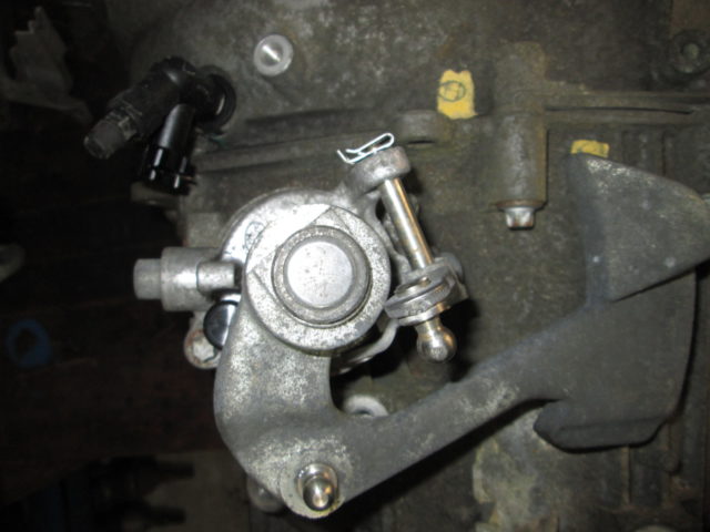
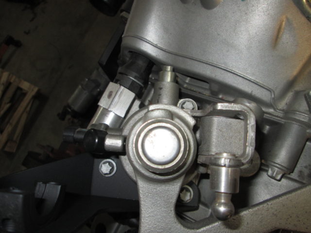
Shifter assembly mounting flange are different (g6 uses 3 bolts, MYJ uses 2)
MYJ gear side of the transmission case is more heavily reinforced with additional ribs as well as 2 additional bolts.
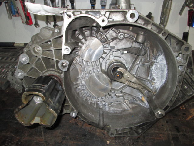
MYJ Bell housing. I used the vice grips to verify the 3.09 final drive. 1.92 turns of the input shaft = 1.0 turns of the tripod in 6th gear:
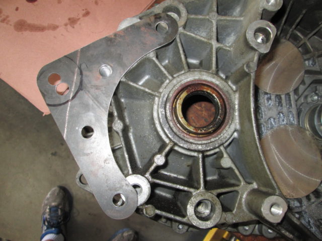
Transmission mount bolt bosses (MT2 bracket):
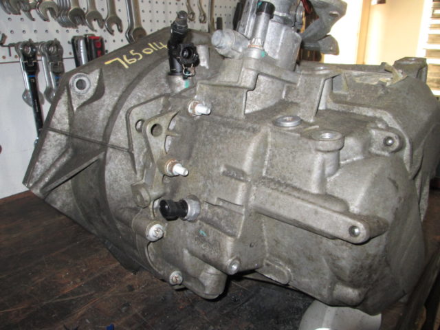
Different clutch line connection. Also notice the reverse gear sensor is moved from the shifter assy to the transmission case.
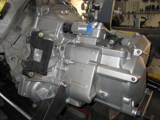
Shifter Assembly differences:
Additional Case Reinforcement (and 2 extra bolt holes) by the lower main shaft - gears 1, 2, 5 & 6):
 [This message has been edited by fieroguru (edited 02-24-2019).]
|
|

|
fieroguru
|
AUG 20, 05:44 PM
|
|
To do the final drive swap, you have to open up the transmission and tear down the gear stacks on the Upper and Lower Main shafts as well as pull the ring gear off the differential.
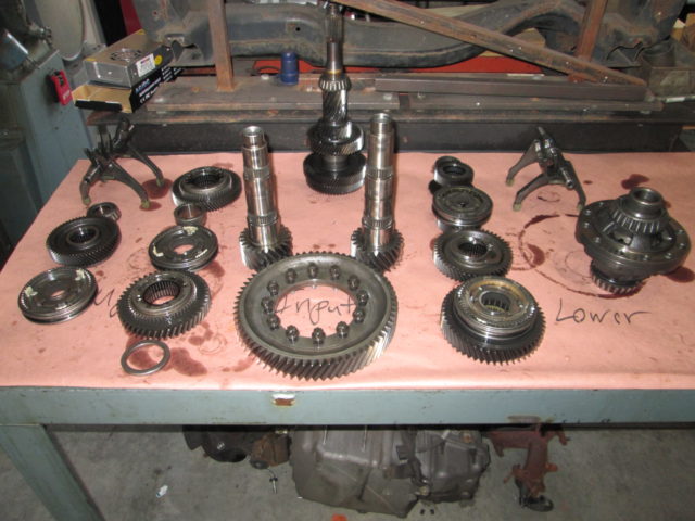
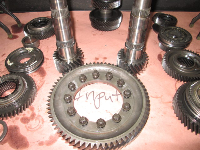
These are the only 3 parts needed. The 3.09 final drive Upper & Lower Main shafts and the ring gear:
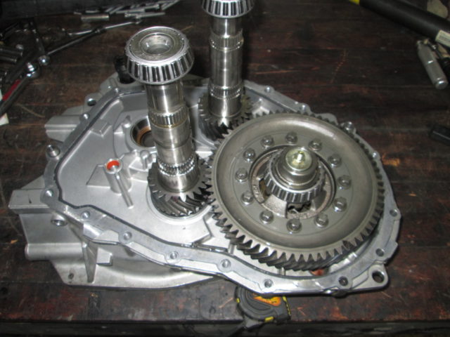
Here they are mocked up in the case:
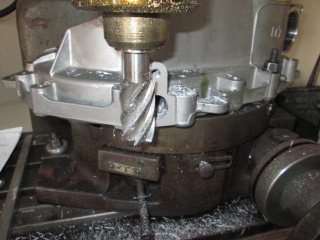
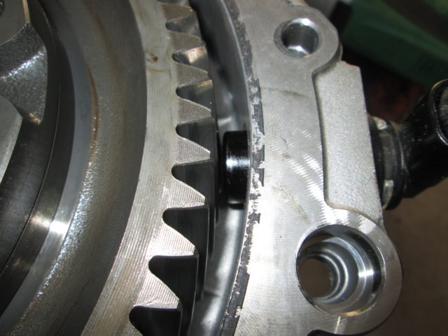
Now, the 3.09 ring gear is smaller than the 3.55 one, so the VSS boss needed milled to move the VSS so it will work with the 3.09 gear.
3.55 VSS placement:
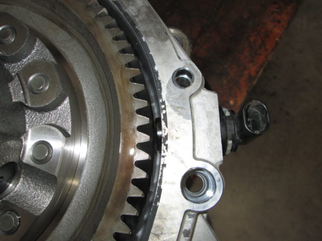
3.09 VSS placement before milling:
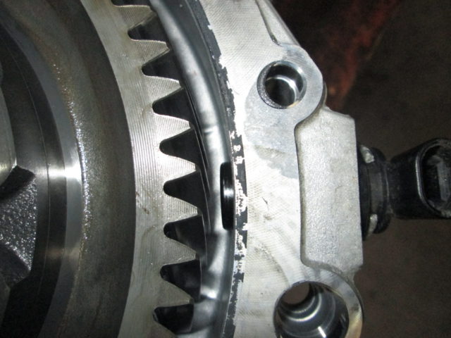
Milling the VSS boss:
3.09 VSS placement after milling:
|
|

|
fieroguru
|
AUG 20, 06:06 PM
|
|
There are no manuals for the F40 transmission, so needed to figure out what the factory preload was for the differential and both main shafts. So once the zero mile G6 F40 was torn down and all gears removed from the main shafts, I reinstalled the factory bearings to the shafts as shown below:
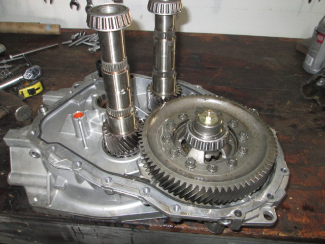
If you notice the center of the differential has a nut and washer sticking out of it. That is an expandable rubber freeze plug so I can spin the differential with a deflector style torque wrench and measure the preload. I did this with just the differential installed, gear side of the case installed and torqued. Once I had the differential preload, I took it apart, added the upper main shaft, reinstalled the gear side case, torqued and measured preload drag again. Then did it again with just the lower main shaft... That gave me 3 preload values that I would try to replicate.
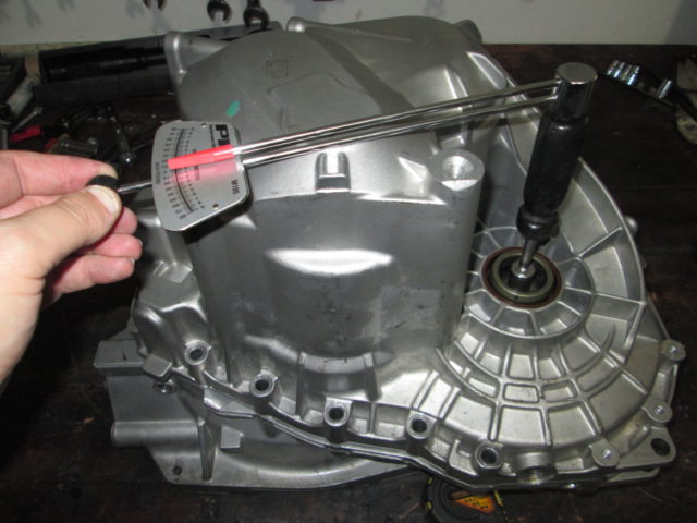
I will keep the G6 differential, just install the 3.09 ring gear, so there is no change to the preload. However, both the upper and lower main shafts will have new bearings installed and will need to have the preload set for the new case using the same method detailed above.
There are no crush washers/spacers, all preload is set with shims between the gear side case and the outer bearing race.
Right now I am waiting on some additional shims to arrive as the lower main shaft was too loose and I needed some thicker shims. I pulled the races from the 3.09 case, but the spacers in that case were still not thick enough. I am also waiting for ARP bolts for the differential gear as well.
More to come later this week as parts arrive...
|
|

|
olejoedad
|
AUG 20, 07:09 PM
|
|
|

|
pmbrunelle
|
AUG 21, 01:31 AM
|
|
|
For those who don't know how to set up a gear-tooth type sensor, it should be as close as possible to the gear teeth, without rubbing.
|
|

|
KissMySSFiero
|
AUG 21, 09:38 AM
|
|
|
You do amazing work on these cars. But you're documentation is hands down better than anyone's I've ever seen. Thank you for that. ------------------
SSFiero@Aol.com
|
|

|
pmbrunelle
|
AUG 21, 12:35 PM
|
|
|
What is your feeling regarding trying to duplicate the drag torque versus duplicating the "axial interference" distance?
|
|

|
Raydar
|
AUG 21, 06:15 PM
|
|
Amazing.
This is pretty much the first thing that I have ever heard about an F40 that might make it worth my trouble to install.
Thanks!
|
|

|
fieroguru
|
AUG 21, 08:22 PM
|
|
| quote | Originally posted by pmbrunelle:
For those who don't know how to set up a gear-tooth type sensor, it should be as close as possible to the gear teeth, without rubbing. |
|
You could also use a feel gauge to verify the current gap, them use a grinder to shorten the boss until you get the proper clearance.
What I did was use my caliper to measure the OD of both ring gears, find the difference, divide by 2 and mill than amount off the boss - a little less than 1/8"
| quote | Originally posted by pmbrunelle:
What is your feeling regarding trying to duplicate the drag torque versus duplicating the "axial interference" distance? |
|
If there was a similar special tool like the 282 and F23 getrag have, then I certainly would have purchased it and used than method. As of now, there are no service manuals on the F40 and no special tools available for rebuilding... so the preload drag will get me back within range and is better than not checking anything.
Also, most of the work to do this swap can be accomplished with basic/inexpensive tools, with the exception of access to a press.
|
|

|
fieroguru
|
AUG 21, 09:23 PM
|
|
Speaking of special tools... there are a few inexpensive tools that can be used, but they need to be modified slightly.
The first task you will need to do is remove the gear side bearing from the main shafts. I used a small 4 jaw puller with a 1/2" button head bolt in the hollow portion of the shaft. Additionally, the legs of the jaws were modified to make them thinner. I used a grinder to remove material from the backside to make the point thinner.
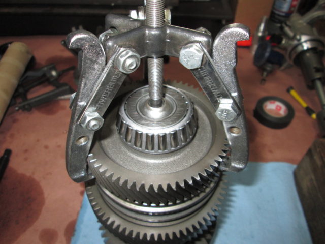
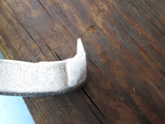
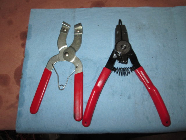
Snap ring pliers and piston ring expander pliers helps as well. Each main shaft has 2 of these snap rings to remove. They are quite strong and a little bit of a pain... I used the snap ring pliers to get the snap ring out of the groove, then I used the piston ring expander to pull them off the shaft.
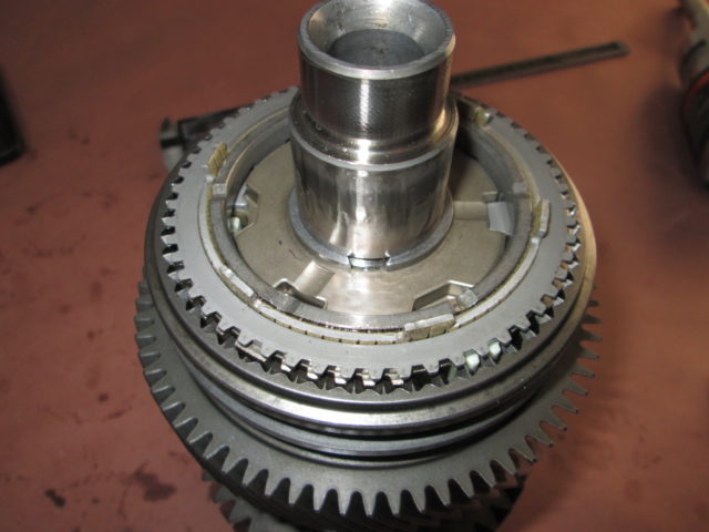
Harbor Freight gear puller. There is a VSS spacer sleeve (the Buick versions have a VSS ring on this spacer) that is pressed on and you need this tool to remove it. This is the tightest press fit of any part on the main shaft. I will add a better pic showing the gear puller setup on this sleeve, but for not these pics will do.
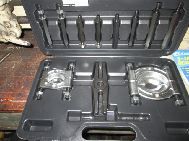
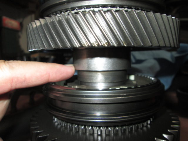
Couple of 4x4 blocks, a 2x4, and a hammer. This last gear set on both the upper and lower shafts is press fit to the shaft, but can easily be knocked free by placing the assembly as shown, resting the 2x4 on the end of the shaft, and a couple of hammer blows.
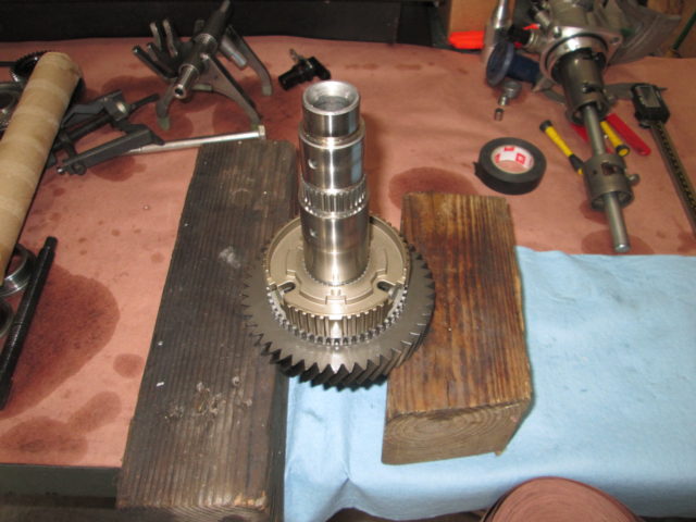
The middle gear set on the lower main shaft that can be removed with 2 pry bars or long screw drivers .
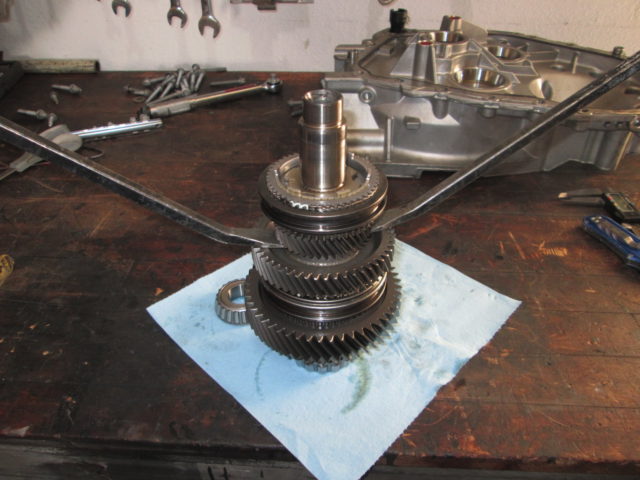
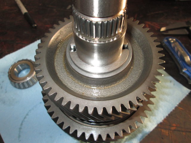
Under the gear set removed by pry bars is a different locking mechanism. There is an outer ring holding two half moon pieces with a locking tab that fits into the hole.
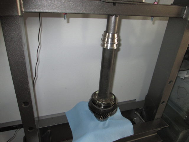
For installation, get a piece of 1 1/2" black pipe. I used a 9" one, but it would be handy to have several shorter lengths so you don't have to keep lowering the press table.
A couple of handy tips...
When you are pressing the splined sections of the syncros onto the shaft, use you hand and raise the gear that is under it, spin it until it snaps into place and once the gear is engaged with the syncro, then press the assembly down while making sure to keep your fingers out of the way. If you don't do this alignment step, you will not be able to press the syncro hub down far enough... you will also bend the ears on the outer syncro cup and have to take it all apart again to fix it...
Also, the bellhousing side bearings protrude past the end of the main shafts. So all pressing operations need to have a spacer or a couple of washers to properly support the shaft. As the press makes contact with the shaft, I made it a habit to spin the lower bearing to ensure it wasn't seeing any of the press load.
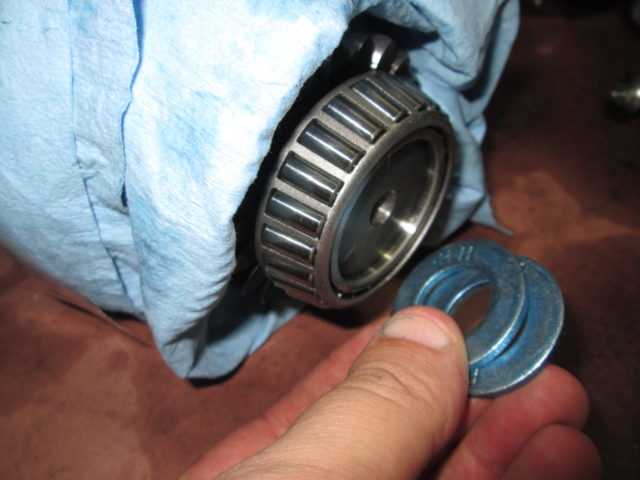
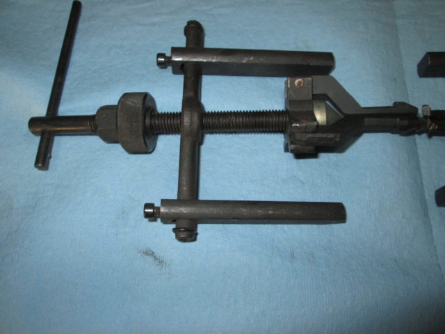
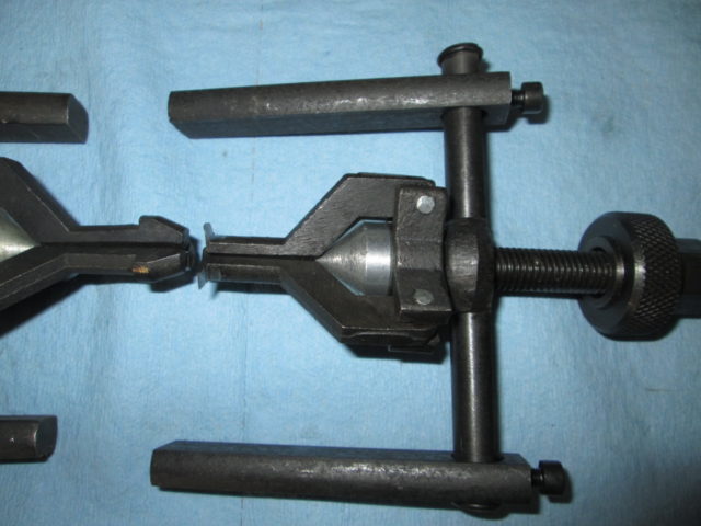
To adjust the main shaft bearing preload, GM put shims behind the outer bearing sleeve. To make any adjustments, you have to pull the outer races. I used a harbor freight pilot bearing puller, but with a few mods. The legs of the jaws were significantly ground down to basically form a point. Most of the material was taken off the bottom, but I did file a slight angle to the top as well. I also ground down the cross shaft to right next to the o-ring grooves. This allows the tool to fit in the pocket for the upper main shaft.
Stock pilot bearing puller:
Modified one:
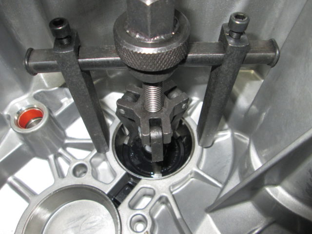 [This message has been edited by fieroguru (edited 08-24-2017).]
|
|
    
  |
|


