
 
     |
| My 4.9 wiring thread (Page 1/16) |

|
Mickey_Moose
|
FEB 02, 02:32 PM
|
|
See Rockcrawls site for info on the engines mounts: http://www.fieroaddiction.com/caddy49c.html
Note: please PM stickpony for ECM programming (VATS/etc) [/shameless plug]
Lately I have been asked a lot of questions, so here is all the info that I use in 1 location:
These notes apply to a 86 coupe using: a 91 Deville and using the 4.9 ECM's cruise control and speedo outputs with the passkey enabled as well as a standard tranny and the Fiero's charcoal canistor (the 4.9 stock canistor has purge controls)
General info:
DO NOT USE ANY TYPE OF CRIMP ON WIRE SPLICE (ie: butt connectors) - always solder and heat shrink your connectors (use weather proof heat shrink in the engine bay to help keep water out).
Pull apart the harness (remove all the tape), run the wires as you see fit, make the connections (ie: tps sensor wiring goes to the tps inputs on the ECM). The real wiring comes where you have to merge it into the Fiero harness.
Method:
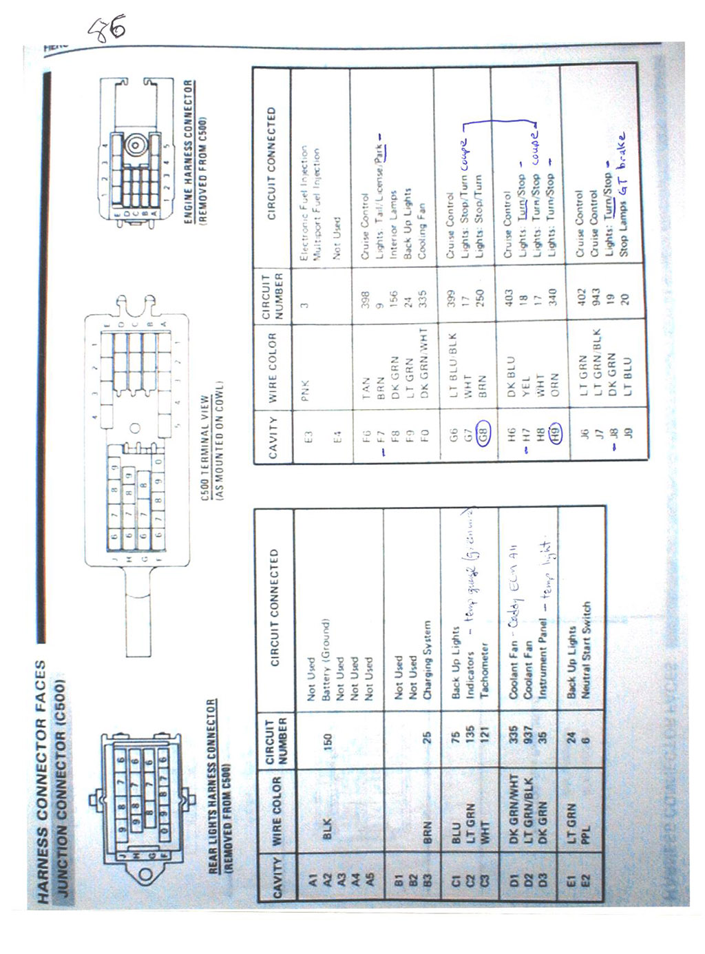
- remove the C500 from the original engine, mark where all the wires attach to the motor, they will more than likely go to the same location on the 4.9 (ie: tach wire goes to tach output on coil, etc).
- I remove the bulkhead pass through from the stock harness using a heat gun and pulling it apart (it is full of hot melt glue). Once clean I install this back into the car.
- remove the C203 connector from the engine harness, cutting any wires as long as I can - do NOT cut the wires that feed the ALDL plug and fuel relay (well you can, but you will just have to reattach them again).
- I cut the firewall bulkhead on the 4.9 harness off.
- remove all tape and loom
- connect up each sensor and lay the wiring on the motor how I like to route them.
- bundle each sensor group of wire together and mark them (ie: tape all the tps sensor wires together and label tps).
- temp tape the bundles together as they will lay on the motor and feed the ends through the Fiero's firewall (through the bulkhead connector).
- remove the drivers seat and sit on the floor
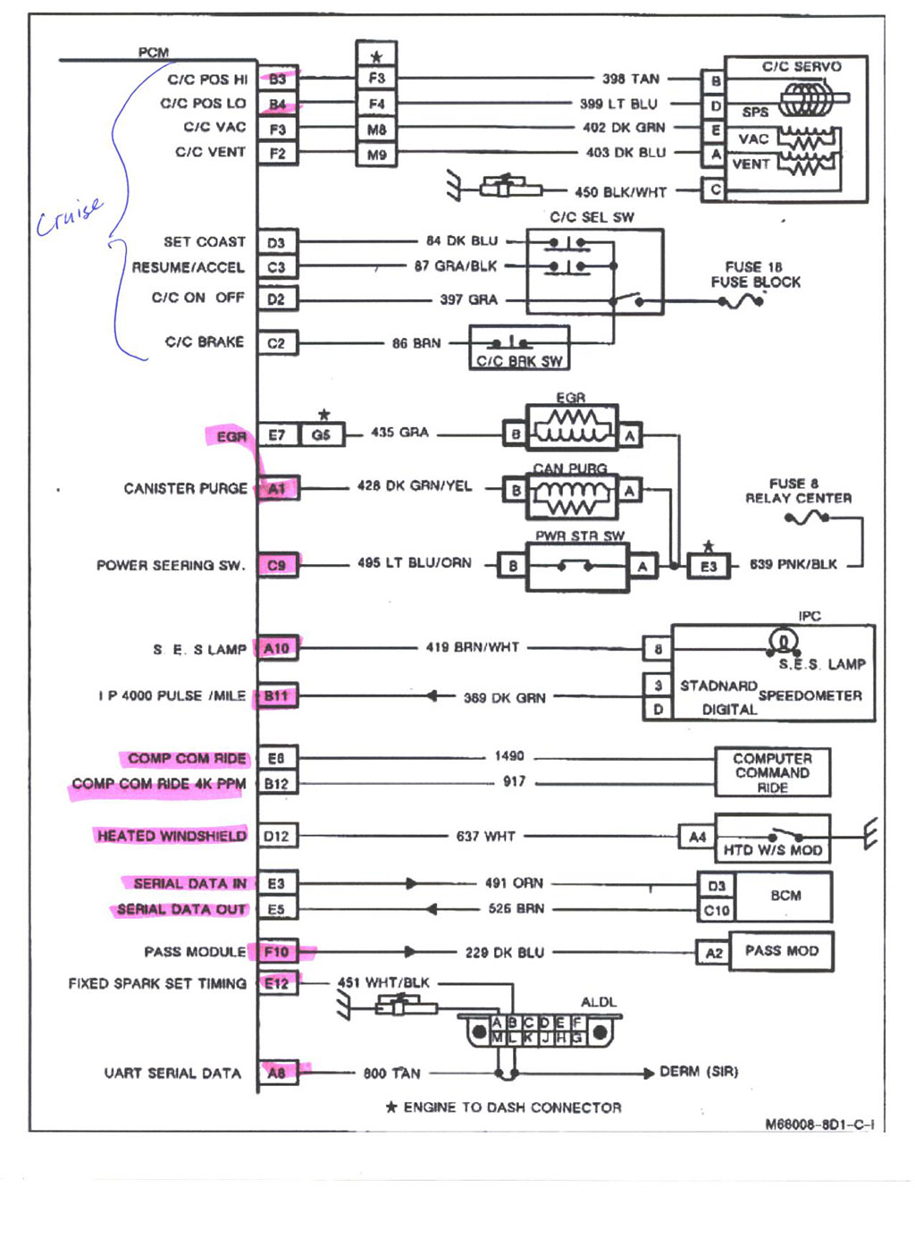
- take each separate group of wires and start splicing them to the correct ECM plug location (cut to length or lengthen as needed). This part you will need is the diagrams that shows the 3 Caddy plug pinouts (2 pages). Once you identified the pins you simply solder the wires together (the wires colors will be the same color so this makes it simple to match up the correct wire).
I usually work with the engine/ECM harness first (connect ECM power/grounds), then the C203 and then the C500. I usually then run the wires for the cruise.
Once the engine is running fine, then I will tape the harness and add any wire looms. I add a couple extra short wires into the bulkhead passthrough and then fill it with hot melt glue (the extra wires are in case something get added later (car starter, alarm, etc that way you don't have to drill excess holes).
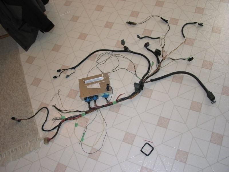
Picture of a semi complete wiring harness (missing: cruise connections, injector harness (on motor) and C500 connector):
Info:
The Pass-Key module (if not programmed out):
Is just a black box it feeds the ECM at pin F10 - you are better off to build the circuit on Rockcrawls site - with the original module you will still have to figure out what resistor value is needed. It can be done as I have done it, but there is no advantage over using the original module (plus it is a lot bigger in size vs the 555 timer circuit). My car currently runs the 555 timer circuit.
Word file with passkey info and circuit diagram (Note: the 4.9 uses the Passkey 1 system):

Power steering ECM input
Has to be connected to +12v
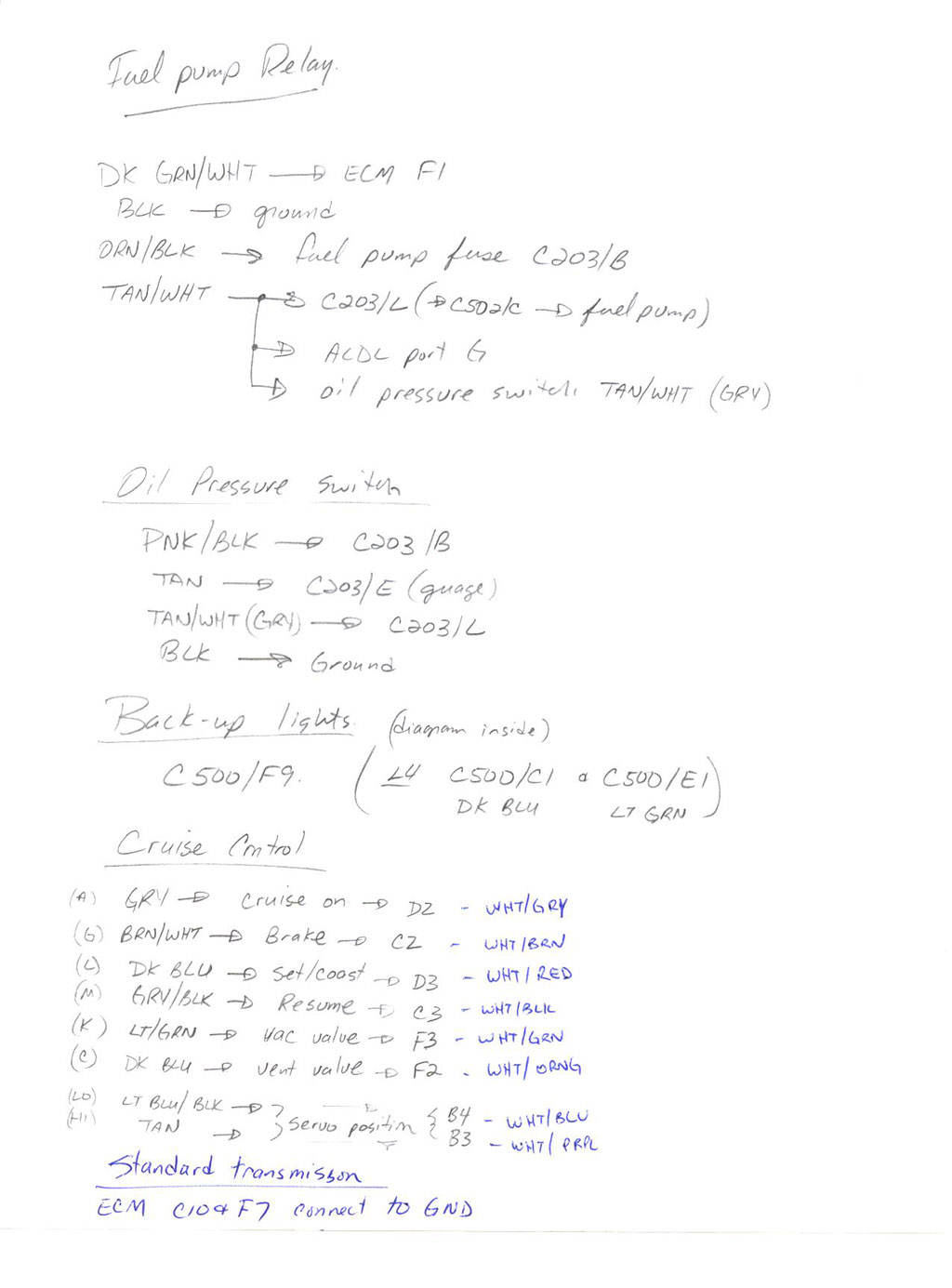
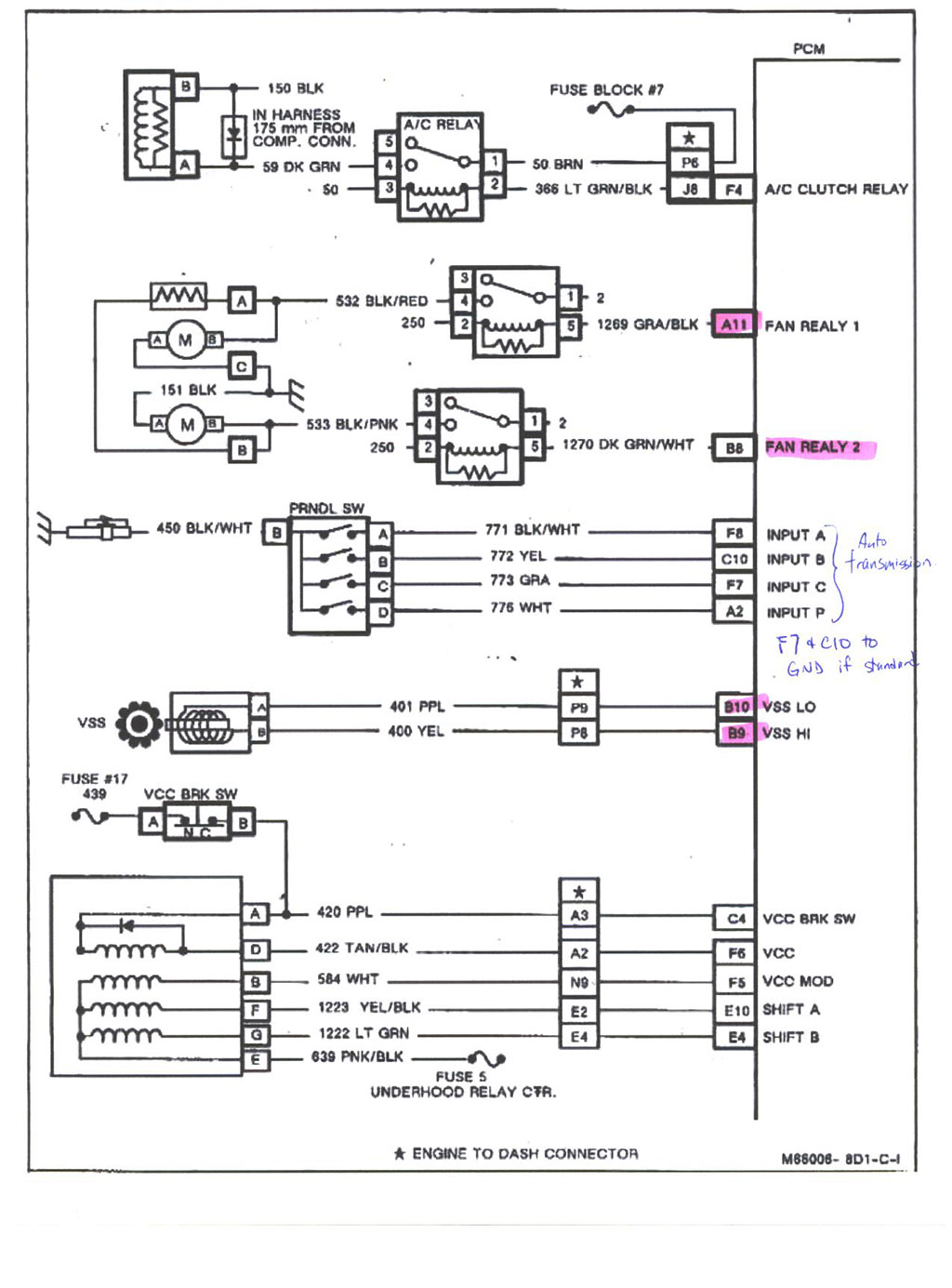
Standard transaxle:
You must connect ECM C10 & F7 to ground, the other transmission pins can be removed.
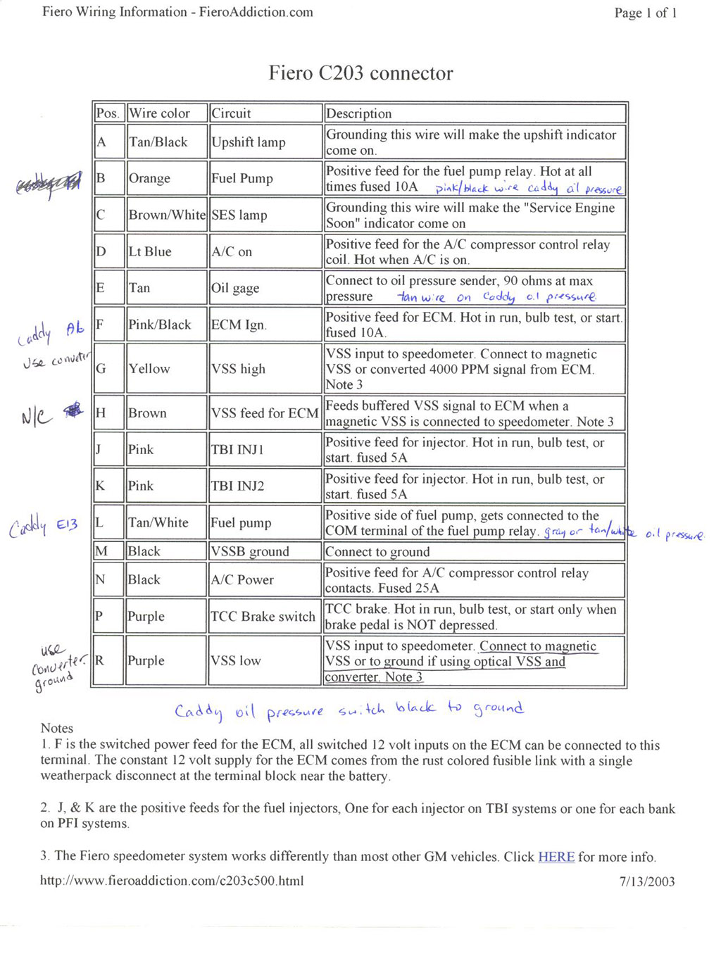
Oil pressure switch:
Use the one for a 2.8 88 Fiero and wires as:
PNK/BLK - C203 positive feed for fuel pump relay (hot at all times).
TAN - C203 oil gage feed
TAN/WHT (or GRY) - C203 positive side of fuel pump, to the COM terminal of the relay also ECM E/13
BLK - ground
Temp sender (also see NOTE):
Located in the thermostat housing (from a 2 wire unit to a 3 wire):
use these parts numbers for the correct sender:
GM 10096181
AC-Delco 213-815
Borg Warner WT3024
CarQuest TX66
Filko CS-43
GP Sorensen 38-5124
Niehoff DR134TA
Napa/Echlin ECHTS4020
Connector comes off a 92 Cavalier or the 3800SC - but most 80-90's GM tps sensor plug will work.
pin "A" BLK wire on the switch goes to ecm "E11"
pin "B" YEL wire on the switch goes to ecm "E16"
pin "C" GRN wire on the switch goes to C500 gage connection
NOTE: Some 4.9's have a temp switch in the side of the head:
1) if you car does NOT have a temp gage and just an idiot light you can leave the stock 4.9 sensor in the thermostat housing - wire this to the ECM, the one in the head gets wired to the idiot temp light on the dash.
2) if you have a temp gage in your car you change out the sensor to the above info and wire, the head temp switch can be thrown out (or used for an additional light that you have added to the dash).
Modify the tach:
many threads here on how to do this.
Speedo:
If you are using the stock Fiero transmission and stock speedo you can simply T off the VSS wires coming from the sender, feed both the ECM and the speedo from teh VSS sender.
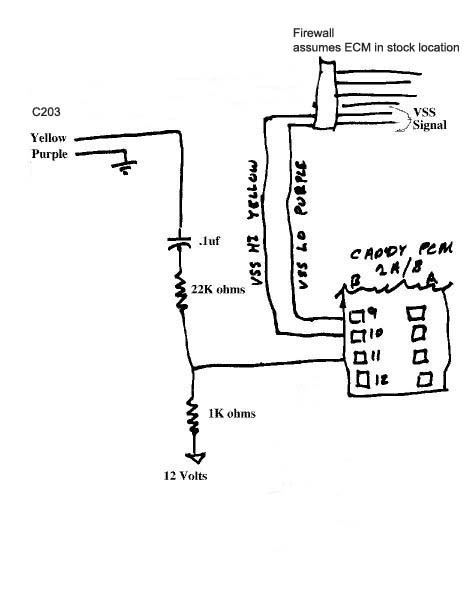
build the speedo clamp circuit as follows (only needed if feeding the speedo from the ECM):
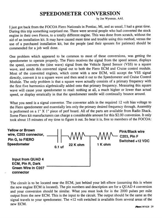
Connects as:
Note: the diagram shows the purple wire in the C203 going to ground, you can leave this out as this wire already connects to ground through the speedo. I normally remove this wire from the ECM side of the C203. The C203 connector opens like a clam shell so it is easy to add/remove wires and pins to this plug neatly.
| quote | Originally posted by Fieroseverywhere:
I just finally got my speedo to work. Thought I'd toss the info out here for those that have problems like I did.
Basically I bought the signal clamp circuit from fieroaddiction, wired it in and... nothing. Speedo would zero out but never moved. SO I decided to make my own circuit. Then I checked the wiring a dozen or so times. Still nothing. Long story short the problem ended up being a bad output on the PCM. Good thing for us there are 2 on the caddy PCM.
So if your speedo doesn't work when you use output B11... switch to B12. Honestly, I'm just glad to know how fast I'm going.
Hey Mickey, Want to add this to the first post with the other speedo info? Could come in handy to some later.
|
|
***ADDED INFO***
| quote | Originally posted by Fieroseverywhere:
Just came accross one more issue that I thought you would be interested in. This time it involves the VSS.
I have had an ongoing issue with my car dropping the VSS signal during heavy acceleration. I had done everything I could think of to fix this problem but nothing worked. I finally cut up a VSS and wired on a pigtail connector because I figured the only remaining issue was the clearance between the VSS connector and the Deville exhaust manifold. Unfortunately this still did not fix my issue.
As I'm sure you are aware there are 2 wires coming from the VSS. Usually yellow and purple. The issue I found involves the way 84-86 fieros are wired from the factory. According to the service manuals for 84-86 fieros (and phsically looking at my 85) the purple wire comes from pin "B" on the VSS, the yellow from pin "A". Looking at the caddy diagrams it appears to be the exact opposite (purple="A", yellow="B"). This also goes for 87-88 fieros. I verified my findings in all the service manuals I could find. It appears GM made a change after the 86 model year.
This may not seem like much but for me it caused a very annoying issue. The speedo works no matter which way its wired. I found this odd actually. Because these wires are reversed the wiring to the PCM was also reversed (because I didn't check the pins, just wire colors  ). The high/low side inputs on the VSS make more difference then I thought. My signal dropping issue is now completely gone and it seems city mileage has increased slightly. ). The high/low side inputs on the VSS make more difference then I thought. My signal dropping issue is now completely gone and it seems city mileage has increased slightly.
It took me a long time to find this problem, almost no time to fix it. Just wanted to keep you in the loop incase you come accross a similar issue. There may be quite a few others that also have this issue and don't even know it. Later Tim,
Caalon |
|
Throttle cable:
the 88 Fiero 2.5l throttle cable (no cruise) is a direct bolt in - these are no longer available new, so you will have to find a used one or crimp an end to your original cable that will fit the 4.9 throttle body.
Tensioner:
System I use (I am told it is similar to Ed Parks): http://www.fiero.nl/forum/A...050818-2-052483.html
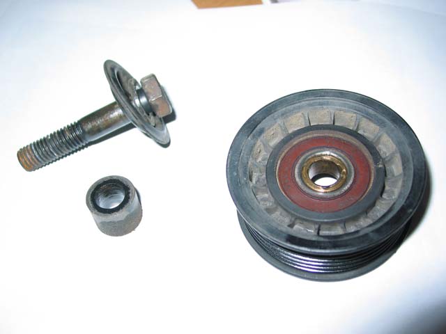
Idler pulley:
Fits a 90 Chevy Astro Van 4.3 V6 NO FACTORY A/C
| quote | Originally posted by Mickey_Moose:
What I did was make a spacer to get the correct distance out from the mounting point (I *think* it is 12 mm tall - but don't quote me on that) and I was able to find a brass bushing in my box of junk that fit inside the bearing and I found a bolt that fit. Not sure what others have done, but here is a picture of what I used:
|
|
Belt size:
This would all depend on your setup. I have usually used 79.5" or 80.0" belts - this ASSUMES, a/c compressor, idler pulley below the alternator and suggested idler near the water pump and Camaro tensioner are used.
Fuel Pump:
The stock Fiero 2.8l (V6) fuel pump works fine, some people have upgraded to using the Corvette or Grand National ones.
Oil cooler delete proceedure , should you wish to go this route:
- from this thread: http://www.fiero.nl/forum/F.../HTML/104610.html#p1
| quote | Originally posted by josef644:
This is not a pro and con over wheather or not to do the bypass, and I ask that you do not take this thread there. If you want to know how to do the bypass, read on.
When I jumped on the 4.9 swap I hadn't heard of having to do a modification to the oil filter adapter to bypass the oil cooler. Mickey-Moose or Fieroguru mentioned to me about doing it and offered up this site: http://www.westcoastfiero.c...l_filter_bypass.html
It didnt tell you much about how to do this. I want to add some information for others thinking about a 4.9 swap, and doing the oil cooler bypass. This adapter is made from cast aluminum and is easy to drill out.
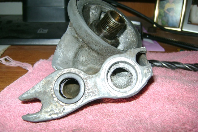
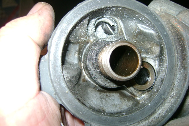
I used compressed air to blow as much 'muck' from the area I would be working on as was possable. You will have to remove the oil filter adapter from the engine. My oil pressure sending unit for the gauge used a 9/16" wrench to take it off of the adapter.
A 15mm wrench is all else that was needed to take the adapter off of the engine. There are two bolts holding it on. The one closer to the distributor does not have to be removed all the way, just back it out about 1/2" or so. Its hole on the adapter is slotted. The other bolt is a long one and it needs to be taken all the way out. You will see this, where the adapter was. Notice the one bolt still in the engine. And the oil 'Mud' That will need to be removed:

I used vice gripes to remove the bypass valve.
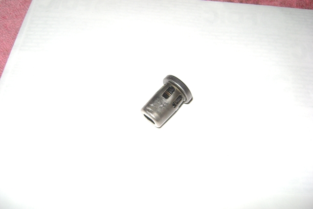
Note the slotted mounting hole on the left:
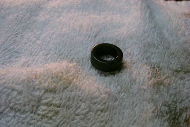
Remove the robber plug next to the long bolt moung part. I just used a small flat blade ot loosen it up, and my thumb nail to lift it out of its bore:
The bit is inserted at an odd angle,from where the seal was removed, to follow the oil passage way in the adapter. I only had about 1/2" of the bits in my drill press, as I didn't want the chuck touching the seal seating surface. Bit just started inside the adapter A 9/32" bit was the size of the hole at first. I made a fist cut with it:
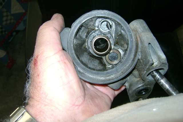
I worked up the sizes one bit at a time untill I got to a 3/8". This was the last size I used. It was the same size as was the inside of the metal pipe sticking up from the engine:
I ran the 3/8 bit till it touched the bottom of the oil passageway. You can see the bit threw the hole where the bypass valve was removed from:
I will clean and paint this piece before I reinstall it. I am gonna reuse the rubber seal I removed. There isn't a gasket needed.
This is a direct quote from EdParks at the Fiereo Factory . I think I read this on Cadero, but its been to long now to remember where. I cut and pasted it in an e-mail to my self:
"use 2 Dorman #090-040 20mm-1.5 drain plugs with a liberal amount of Permatex on the threads" Less problems with leaks I think he said.
Any other suggestions are welcomed
Joe Crawford
|
|
Auto transaxle wiring:
I am just providing this info, I have not personally done one:

With regards to wiring a 94 transaxle up to a 91 ECM ( http://www.fiero.nl/forum/A...070315-2-077614.html ):
| quote | Originally posted by opm2000:
on your 7 pin round transmission plug:
-the wire in G should go to B
-the wire in F should go to A
-the wire in B should go to C
|
|
AC info:
A/C delete pulley (in case you not using a/c, but still want the ertra belt wrap on the water pump):
http://www.am-autoparts.com...urce=YahooShoppingSF
AC wiring:
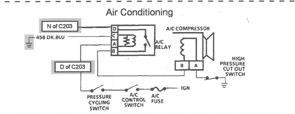
| quote | Originally posted by josef644:
M_M
I had ordered some compressor 'O' rings this last weekend. I only had one 'O' ring on my compressor. They arrived today, and were sealing washers, not compressor port 'O' rings. I spent about two hours on the net looking for a number to try to look up to get the correct ones. I located OEM # 02724674, which is AC Delco #1530169. I called O'Rrilly's in Huntsville, TX They had 9 in stock. 83 cents each. I drove the 32 miles each way and bought me 4 of these. If I was asking for these by application, 91 Cad Deville, AC & heating, compressor seals, etc they were not listed. I found this OEM number at http://gmpartsgiant.com/
This was a difficult item to find. I had been to 4 different parts houses trying to find these, I took my one in my possession, most said they had nevere seen one like these, as they are sort of oval shaped.
The guys at O"Riley's didn't even know they had these until I gave them the AC Delco number. This number was hard to find and might be helpful to someone else trying to AC their 4.9 using the Caddie's compressor.

Joe
|
|
Alternator info:
Also see:
http://www.fiero.nl/forum/A...090219-2-081509.html
http://www.highampalternato...om/cs130_sbpage3.htm
http://www.autorewire.com/t.../Delco10SInandd.html
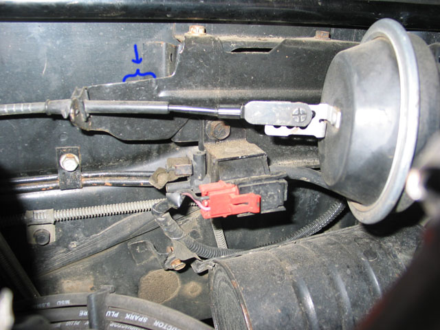
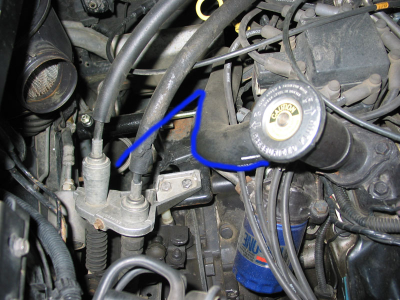
Fiero cruise bracket:
If you are going to use the stock Fiero cruise system with the 4.9, you can use the 4.9's cruise cable, but you will need to modifiy the bracket that holds the vacuum solenoid. It needs to be made longer. Here is a picture of mine, the area indicated in blue was added to give the length needed.
Also, this was brought to my attention, so something to keep in mind (for some reason it does not apply to my car):
| quote | Originally posted by sanderson:
On Fiero power goes through the "on" switch on cruise control stalk and then splits. One split goes directly to the ECM (late 4 cyl) or cruise control module (V-6). The other split goes to a brake/clutch switch(es) and then to the ECM (late 4 cyl) or the cruise control module (V-6). When wiring up a Caddy the direct wire goes to D2 and the switched wire goes to C2. If your Fiero did not have cruise the brake switch is not there and IIRC neither are the wires.
On auto Fieros there is another brake switch. Power goes through it and then to torque converter clutch. This goes through C203-P and into the engine harness to the transaxle. I'm not sure if this switch and wiring is there on a manual Fiero. When wiring up a Caddy the C203-P wire goes to the TCC but is also splits and goes to C4 on the PCM.
With a fresh PCM in my car the "brake depressed" message on the scan tool is working. I can turn it on or off by depressing the brake pedal. I do not have the cruise switched on so I have NO POWER to D2 or C2. The brake depressed message is not on normally. I can turn it on by depressing the brake pedal but it has to be the second brake switch wired to C4 that it causing this to happen.
Mickey Moose said he has no power to C4 and does not normally have the the brake depressed message. If he's running a non stock chip maybe this was programmed out. He does get it the brake depressed message if the cruise control is ON and he steps on the brake pedal.
It appears that either brake switch can activate the brake depressed message. But the PCM only looks at C2 if it sees power on D2.
If the brake depressed message is normally on, I still think power has to be supplied to C4 to turn it off.
|
|
...Verified...
| quote | Originally posted by Fieroseverywhere:
Hey man. I stumbled onto the solution to the "brake depressed" message I hadn't been able to get rid of. It ended up needing +12v to PCM pin C4 (VCC brake switch input). Now I'll be able to hook up the cruise control. Thought I'd let you know in case you want to add it to the wiring thread. |
|
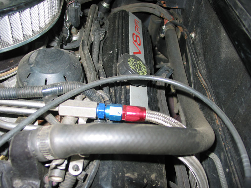
Fuel lines:
From a V6 car, you will need (with thanks to Fieroseverywhere for the part numbers and links):
14mm o-ring to -6AN - you need 3 of these
http://store.summitracing.c...700+115&autoview=sku
16mm o-ring to -6AN - you need one of these
http://store.summitracing.c...700+115&autoview=sku
Plus hose...
Vacuum hoses:
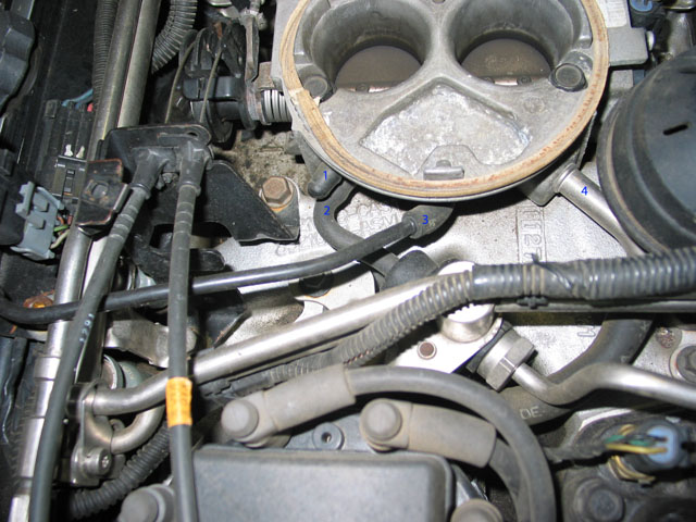
1 - capped off, this would go to the vacuum port on the automatic transmission
2 - regulator on fuel rail
3 - MAP sensor
4 - brake booster (attaches to the filter that is on the firewall)
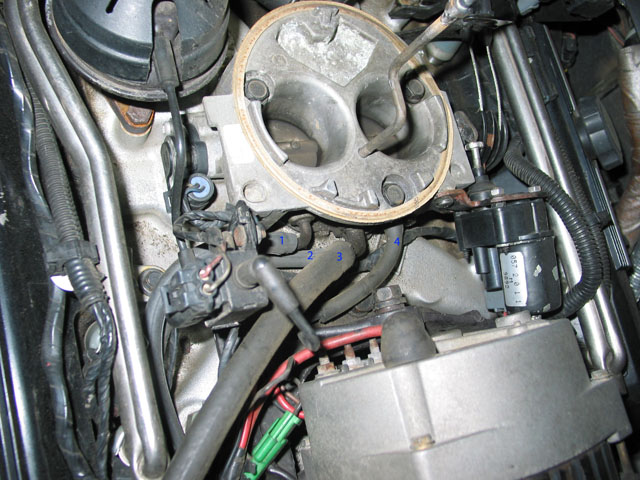
1 - goes to the charcoal canister (small port) marked "control vac" - also has a T inline to feed the cruise vac can
2 - goes to the larger port on the charcoal canister.
these hoses connect to the steel lines that are running along the trunk. NOTE: I am running the Fiero's canister, the Caddy one will hook up the same, you just have to add the wiring to the ECM for it.
3 - PVC Valve - I rotated the tube so it points towards the rear of the car
4 - EGR solenoid
Coolant hoses:
Here is the small hose that is coming off the thermostat housing, feed to the heater core. On my car there is a metal tube that runs along the frame in a channel (the red clip is holding the metal tube to the metal body. The people that do not have this hose here have modified the thermostat housing so that this hose runs along the big one off the thermostat housing - REMEMBER my car was a 4 cyl, so you may not have the metal tube.
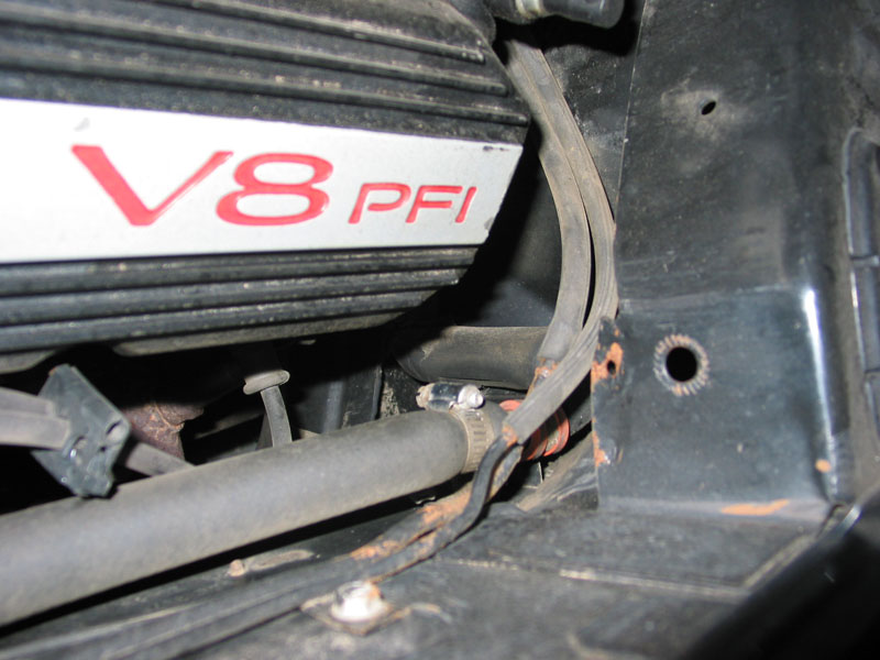
This picture shows the metal tube a bit better - it is wrapped in a black foam (I assume is for heat retention).
Shows my thermostat housing (modified by welding the top half of the 4 cylinder on to the base of the original 4.9 housing). This hose feeds down to the rad tube that runs under the drivers side of the car (the stock 4 cylinder hose works just right here with a small extension near the bottom to reach the tube. The blue line sort of shows the path.
The tube that runs under the passenger side of the car feeds the larger port on the water pump, the stock Fiero hose that was here works on the 4.9, the smaller port on the water pump connects to the return heater core hose, again the stock Fiero hose that was connected here gets used on the 4.9.
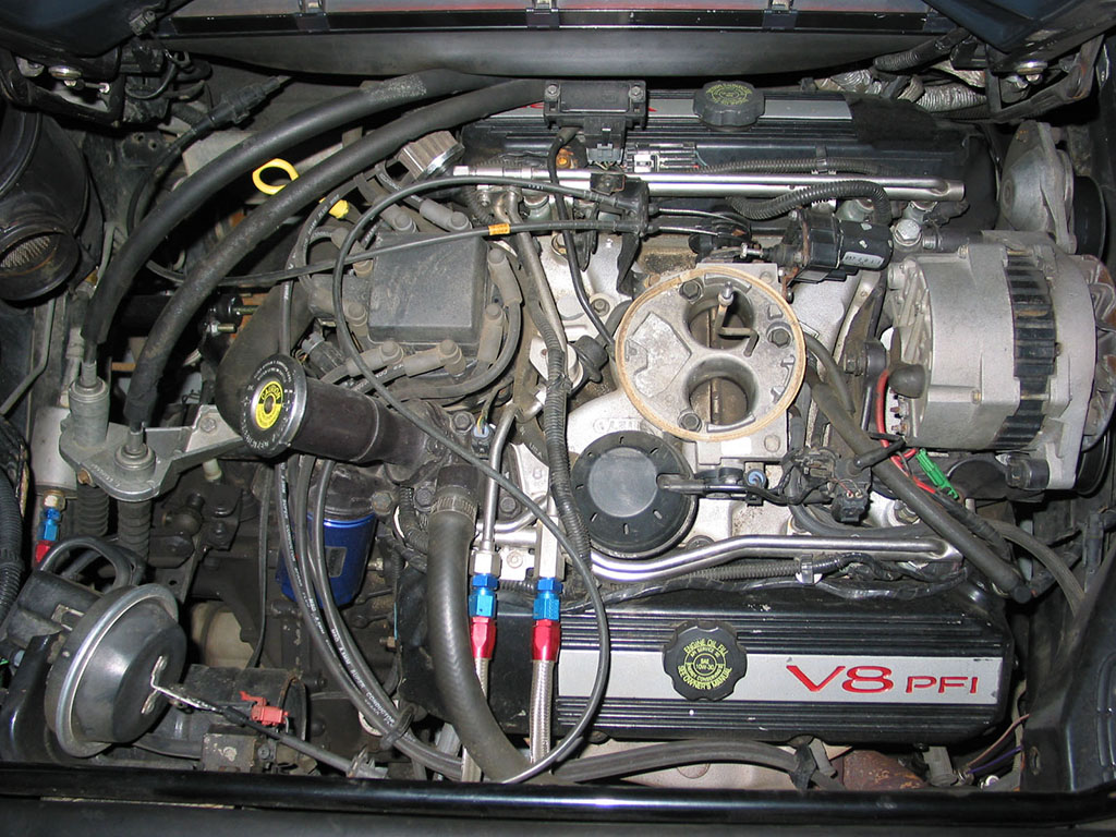
And here is an overall picture of my engine bay - you can see my fuel filter to the left of the shifter cables - the other line runs underneath it:
***ADDED INFO***
| quote | Originally posted by Dizzixx:
I redid my wiring diagrams. They were produced almost entirely using information from this thread so credit is due to Mickey_Moose and others that helped get this out there. These are specifically for a 92' 4.9 single O2 into an 87' Fiero Gt Manual. Hope they are of use to someone. This is the second iteration and I have worked out the bugs but as always use at your own risk.
http://depositfiles.com/files/zymub91vy
|
|
Scans of my wiring notes:
Left orignal size to keep it readable.
NOTE: credit to Rockcrawl as this is where the original diagrams came from before I scribbled all over them. 
ALDL Plug:
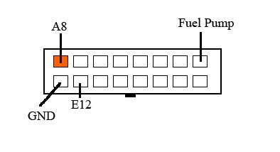
Highligthed areas are 'must use' connections (in most cases):
NOTE: it was pointed out by ImperfectTruth that A7 is not highlighted and YES this is needed
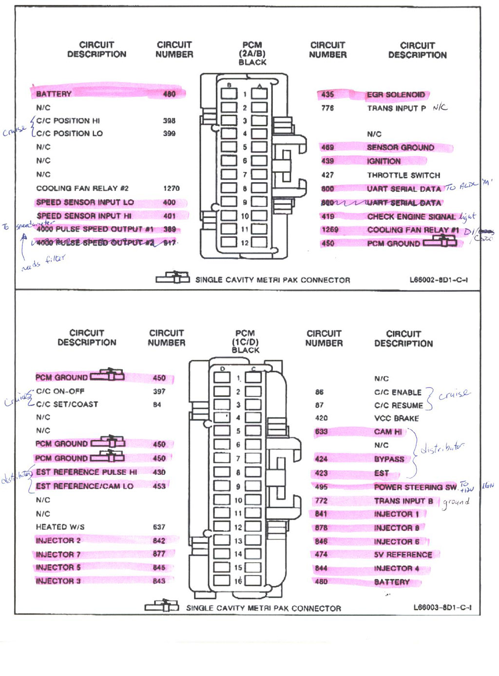
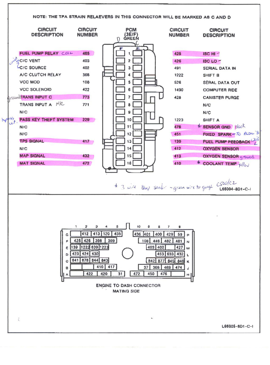
Note: there is a correction in the following for the grounds - it shows D5 as connected to ground when it should read D6:
Thanks to olejoedad for pointing this out
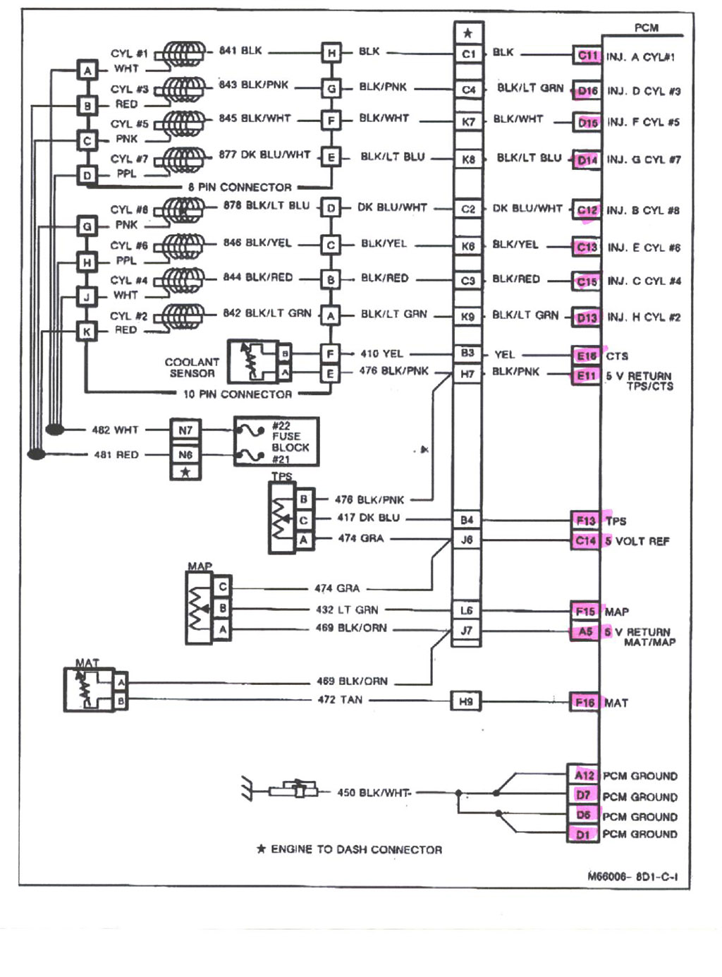
Note: there is a correction here for the EGR - the highlighted area is correct (EGR=A1):

And here is a copy of the 92-93 service manual that I received courtesy of Fieroseverywhere:
92-93 4.9 Service Manual
Just an FYI on how the ECM determines what gear the car is in
F8, C10, F7 and A2 provide a binary code input to the ECM to tell it what gear the car is in - code 91 indicates a unknown code is inputted.
SpECiFiCLlY:
in this order of F8, C10, F7, A2
P = 0100
R = 0011
N = 1010
D = 1001
3 = 0000
2 = 0101
1 = 1100
So, in a manual car when you tie C10 and F7 to ground (the pins are tied high internal to the ECM) inputs 1001, which tells the ECM it's in drive. Technically speaking A2 is what GM is calling a parity bit and you have a 3 digit binary code.
Hope that helps and answers any questions,
Tim
BIN files for the 2240 PCM (what I have) can be downloaded from here: https://drive.google.com/dr...AI0g4?usp=share_link
NOTE: I do NOT recall if VATS has been disabled in these files or not - you will need to verify in Tunercat.[This message has been edited by Mickey_Moose (edited 02-11-2023).]
|
|
|
|
SeafordMX
|
FEB 02, 05:04 PM
|
|
|
|
|
Carver1
|
FEB 02, 05:18 PM
|
|
|
Awesome post! I converted this w/pics into a 2MB word document. With your permission, Tim, I can email it to anyone who needs it.
|
|
|
|
sanderson
|
FEB 02, 05:41 PM
|
|
The VATS (passkey) can be defeated with a VATS bypass module. They are available from Baker Electronix (e-bay store) for $25. There are two versions 30 Hz and 50 Hz. 30 Hz works for 91-93 and 50 Hz for 94.
Edit to add website for Baker Electronix - http://mysite.verizon.net/vze7erz1/[This message has been edited by sanderson (edited 02-03-2009).]
|
|
|
|
Dizzixx
|
FEB 02, 08:02 PM
|
|
Rofl... looks like someone got sick of having to answer my questions. Or at least didnt want to do it again. 
Looks great, this information is absolutely invaluable. Thanks again.
|
|

|
olejoedad
|
FEB 02, 08:52 PM
|
|
|
Great post - good work - a plus for you!!!
|
|
|
|
Carver1
|
FEB 02, 08:53 PM
|
|
|
plus from me also. About as complete as it gets right there,
|
|
|
|
Mickey_Moose
|
FEB 03, 10:18 AM
|
|
Please note that I have added a couple more pictures/info (to be 'more' complete): temp sensor, speedo converter and cruise. Also reorganized...
...and as soon as I find my passkey diagram, I will also add it to the post.
Feel free to 'share' this info with others, as it is meant to be shared and no secret (it's all been posted already, just not in one post).  [This message has been edited by Mickey_Moose (edited 02-03-2009).]
|
|
|
|
josef644
|
FEB 03, 12:30 PM
|
|
You have a + from me, I am planning on gathering the 4.9 and other necessary items for this swap this summer into Fiero # 3.
Joe Crawford
Texas
|
|
|
|
hklvette
|
FEB 10, 08:39 AM
|
|
|
since i plan on doing a 4.9 in the future, a + from me.
|
|
|
|