
 
     |
| Relocating Antenna to under the Fender (Page 2/4) |

|
Leviathan
|
JAN 11, 10:20 AM
|
|
| quote | Originally posted by Raydar:
I don't know if this was mentioned elsewhere, but you should put a piece of plastic tubing over the antenna. If the metal mast touches the spaceframe it will likely kill the signal.
Also, having the antenna in close proximity to the spaceframe will tend to shadow the signal, and make the antenna very directional. (Sounds like you already know that.) |
|
Yeah, Great point. I cant remember where i read it, but somebody put an antenna on both sides of the car and said that that gave them the best reception (better than the stock antenna location). I have to assume that he put an antenna on both sides because of what you mentioned. Im sure the spaceframe blocks a lot of signals from the other side of the car.
During my commute to work, i go in and out of range of a few radio stations. I know where the signal normally ends. When i get the car back to together, im curious to see how much the antenna relocation hurts my reception.
|
|
|
|
theogre
|
JAN 11, 11:16 AM
|
|
Fender is low plus frame is ground plane and hides the antenna from getting good signal, especially at medium to long distances.
I just put a wire along the edge of windshield and connected to antenna base.
Hides the antenna w/o killing signal. Did that because kids break off antennas.
Two antennas can cause signal problems and often not a simple as splicing two antennas to a wire.
You should read real antenna data, not BS posted on many forums.------------------
Dr. Ian Malcolm: Yeah, but your scientists were so preoccupied with whether or not they could, they didn't stop to think if they should.
(Jurassic Park)
The Ogre's Fiero Cave (It's also at the top and bottom of every forum page...)
|
|
|
|
Orig88GT-NC
|
JAN 11, 05:48 PM
|
|
I think ( theogre ) is onto something with just attaching a wire to the Antenna Base stud  . .
It would give you more flexibility in your mounting, and you might be able to bring the wire up the A-Pillar by carefully tucking it between the drip rail and chassis as an option.
The length of the wire is important for good radio reception,( advised to me by people who know alot more about radios than me ) so I would start with a wire that is 32" long ( same as the original antenna mast)
and go from there.
In your original question you asked about ......
* the antennae base stud size?....measured this mourning, its metric ( M6 x 1.0 ) ~ 8mm in length.
* and does it come through the fender? .... No, it sits below by about (3/16" to 1/4")

|
|
|
|
theogre
|
JAN 12, 01:16 PM
|
|
| quote | Originally posted by Orig88GT-NC:
I think ( theogre ) is onto something with just attaching a wire to the Antenna Base stud .
It would give you more flexibility in your mounting, and you might be able to bring the wire up the A-Pillar by carefully tucking it between the drip rail and chassis as an option.
The length of the wire is important for good radio reception,( advised to me by people who know alot more about radios than me ) so I would start with a wire that is 32" long ( same as the original antenna mast)
and go from there. |
|
OE radio uses AM and FM and means different bands. (AM 530-1610KHz, FM 87-108MHz.)
will get different tuning on a band but really is not a big problem for receiving. A poor tune of antenna is more of a problem in rural areas because that will kill channels.
Is a big issues using any 2-way radio. Miss-match eats power in transmission and can ever kill the radio's output transistors.
Perfect match to a channel can vary a lot... long story, google: 1/4 wave antenna length
Good calculator is http://www.csgnetwork.com/freqwavelengthcalc.html
Examples:
1/4 wave antenna for X channel = Y
108MHz = 27.33 Inches (high FM)
100MHz = 29.52 Inches (middle FM)
88MHZ = 33.55 Inches (low FM)
1000KHz = 2952 Inches/246 Feet (middle AM)
Just for fun...
27MHZ = 108 Inches/9 feet for CB radio band. Is why "whip" antennas are 9 feet. All Shorter uses load coils.
WiFi 2.4GHZ band = 1.23 Inches for 1/4 wave, 4.95 full wave
Your 32 inches means is tuned for FM band but a few inches off won't matter much. AM can use same antenna
especially because you aren't transmitting.
Bigger issue is the antenna hidden in the fender. Car's body is the ground plane for all antennas attach to it. You don't want your antenna buried in the car's metal to get a good signal. (google: antenna ground plane)
Have antenna close to A pillar isn't the best but likely better then under fender. I get most channels using a wire under glass trim even driving in rural areas.
|
|
|
|
Raydar
|
JAN 12, 08:23 PM
|
|
Ogre's idea about using a wire inside the windshield trim sounds like a good idea.
In reality, you could probably run a wire underneath any body panel and receive a decent signal, provided that you weren't using metallic paint. The metal flakes in the paint might tend to block the signal.
Ideally, you would want to keep the wire as far as possible from the metal structure of the car, as he mentioned.
My dad used to experiment with antenna design for some two-way equipment that we had. He got the best results from some of the damnedest things.
Play around. Figure out what works.
I realized, when I bought my G6, that the radio antenna looks like part of the rear window defroster grid, except that it's at the top of the window, and separated from the real defroster by a couple of inches.
In the 60s, GM used wires embedded in the windshield glass for radio antennas. They sort of worked.  I'll bet they would have worked better for FM, had it been in common usage at the time. I'll bet they would have worked better for FM, had it been in common usage at the time.[This message has been edited by Raydar (edited 01-12-2015).]
|
|

|
Patrick
|
JAN 12, 08:47 PM
|
|
| quote | Originally posted by Raydar:
In the 60s, GM used wires embedded in the windshield glass for radio antennas. They sort of worked.
|
|
I remember that as well, but I think it was bit later... maybe the 70's. Anyway, it was back when we were young and fearless. 
|
|
|
|
theogre
|
JAN 12, 09:13 PM
|
|
| quote | Originally posted by Raydar:
In the 60s, GM used wires embedded in the windshield glass for radio antennas. They sort of worked. I'll bet they would have worked better for FM, had it been in common usage at the time. |
|
Early 70s... Family had a GM car w/ this. Other markers still use this plan.
Two fine wires you could see.
They work good in most places.
is hard to see because tint... start at bottom then bends 90° about 2-3 inches at top
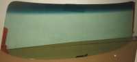 | | CLICK FOR FULL SIZE |
source: ebay listing[This message has been edited by theogre (edited 01-12-2015).]
|
|
|
|
Leviathan
|
JAN 13, 09:19 PM
|
|
Awesome information Ogre! Great job educating about wavelength.
Real Fast, i fixed my pictures in the first few posts, thanks Patrick
I wouldnt be happy with myself until i found out how much signal i lost with the antenna being placed under the fender vs the stock antenna location vs a wire on the dash.
When i was in college, we used to use these extremely expensive devices called Spectrum analyzers. They are used to probe RF electronics and display the amplitude of signals at various frequencies. For example, if you make a 1Mhz sine wave generator, you will always have harmonics that appear in the signal (2 Mhz, 3 Mhz, 4Mhz etc.) The harmonics will always be less than the primary signal, but can cause problems in some circuits. Normally, spectrum analyzers cost a minimum of $2,000 - $4,000 for a decent one.
Picture of a Spectrum Analyzer:

I found an incredible device for $20 that allows me to do exactly what a spectrum analyzer does between the frequencies of 22Mhz to 1.7Ghz. It was originally designed to be a TV tuner that allowed you to watch analog TV channels on your computer. It didnt take long before some geniuses realized that the device could do much more than watch TV. With a small change to the driver on your computer, it allowed the users to adjust the frequency that the device filtered into. It also allows the device to sweep through every frequency and display the amplitude of the signal at all of the frequencies like a spectrum analyzer.
Here is their homepage: http://www.rtl-sdr.com/about-rtl-sdr/
I plan on plugging in the antenna to this device and using an FM transmitter to measure the signal strength at various angles of the fiero with the antenna in various orientations. Ogre is right, there is a lot of BS out there, hopefully having real data will debunk some of this. Who knows, we may be surprised with the results.
|
|
|
|
theogre
|
JAN 13, 09:39 PM
|
|
| quote | Originally posted by Leviathan:
Awesome information Ogre! Great job educating about wavelength.
Real Fast, i fixed my pictures in the first few posts, thanks Patrick |
|
thanks
please use [img thumb] not [img] for big pictures.
|
|

|
Patrick
|
JAN 13, 11:33 PM
|
|
| quote | Originally posted by Leviathan:
I found an incredible device for $20 that allows me to do exactly what a spectrum analyzer does between the frequencies of 22Mhz to 1.7Ghz. It was originally designed to be a TV tuner that allowed you to watch analog TV channels on your computer. It didnt take long before some geniuses realized that the device could do much more than watch TV. With a small change to the driver on your computer, it allowed the users to adjust the frequency that the device filtered into. It also allows the device to sweep through every frequency and display the amplitude of the signal at all of the frequencies like a spectrum analyzer.
Here is their homepage: http://www.rtl-sdr.com/about-rtl-sdr/
|
|
Interesting stuff. If you feel so inclined, you might like to start a thread in O/T to discuss this further. A few of the guys who hang out there might enjoy hearing what you can do with this inexpensive technology.
|
|
|
|