 
     |
| Bumpsteer bracket (Page 2/6) |

|
wftb
|
MAR 07, 04:04 PM
|
|
Coilover installed temporarily , holding up the weight of the car .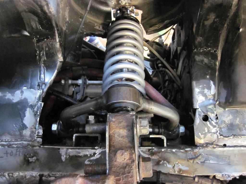
|
|
|
|
wftb
|
MAR 07, 04:13 PM
|
|
View of the balljoint and arm with coilover removed looking down threw the top of strut mounting hole .Lots of clearance for balljoint .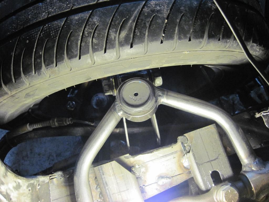
|
|
|
|
wftb
|
MAR 09, 05:25 PM
|
|
Here is a picture of the assembly off the car . The angles are just random for the sake of a picture .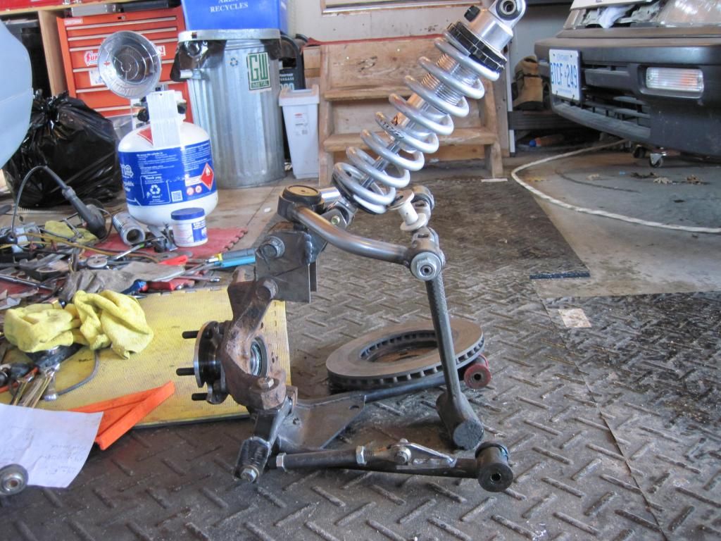
|
|
|
|
wftb
|
OCT 20, 02:32 PM
|
|
Just keeping this thread going for people that do not visit the construction zone .I now have the car supporting itself on its new suspension .Still a lot of things to do to make it roadworthy again but everything looks very promising .
This pic shows the brackets that hold the upper coilover mounts in place .I had hoped to make these adjustable , but there is not enough room on the passenger side to do that .I added compression bumpstops to the coilovers as there is not a huge amount of travel .I think it will be adequate , but these bits of rubber are cheap insurance against breaking expensive shocks . 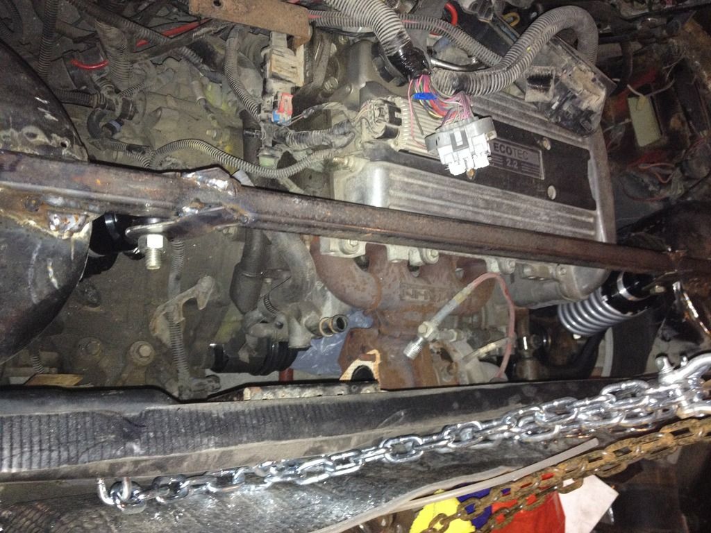
|
|
|
|
CarolinaRigman
|
OCT 26, 10:32 PM
|
|
An off topic question if I may.
Did you see any evidence of the F23 having a differential center line of about 10 mm
toward the passenger side when you put your axles and everything together on your
rear spindle assemblies together? Or maybe you saw this ahead of the game and compensated for it?
Sounds kinda crazy, but my psychiatrist couldn't answer my question!
|
|
|
|
wftb
|
OCT 27, 10:01 PM
|
|
|
Like your shrink , I really cant tell you .When I first put it in the car I just hung it over the cradle and measured to make sure it would not hit anything and bent up some steel for mounts and carried on .More info is in my build thread , ecotec swap , construction zone . Thanks for the reply , have a great day .
|
|
|
|
wftb
|
OCT 28, 12:20 PM
|
|
In order to be able to align the new suspension , I made some eccentric washers and welded on some retainers to the upper arm supports .If you look closely , you will see some slots in the washers so they can be turned with a straight blade screwdriver .There is also a reference line that is scribed into the arm mounts so that the arms can be set at the same angle to the frame as the lower arms . The upper arms are adjustable to set the camber and by using shims between the arms and the eccentrics I can adjust for slope of arms relative to the ground and amount of anti squat can be adjusted as well .Toe in/out is adjusted by the link on the lower arm .
 [This message has been edited by wftb (edited 10-28-2015).]
|
|
|
|
wftb
|
FEB 22, 10:25 PM
|
|
My new rear suspension is completed and I have done some preliminary testing that shows that it works .There is going to be lots of fine tuning for sure , but that is why I made it fully adjustable .I took it for for a ride around our backyard today (1.2 acres) and I am very pleased with the results.I thought I would post some more pics on this thread just to show that I have accomplished what I set out to do : build the first SLA rear suspended stock wheelbase fiero .


More pics and info are on my thread in the construction zone
|
|
|
|
Blacktree
|
FEB 22, 11:08 PM
|
|
That looks pretty cool. 
My concern is that your toe links will have enough leverage against the add-on brackets to work them loose. That's what stopped me from making such a bracket myself. I just didn't have enough confidence in the design. Hopefully, I'm just being paranoid.
|
|
|
|
wftb
|
FEB 22, 11:32 PM
|
|
|
Thanks for the reply . The brackets cannot come loose , they can only bend under extreme forces .The way i built them , the brackets box the wing on the spindle - they cannot flex or move except where they attatch to the rod end .And that would only be the kind of force you would encounter during an accident - the length of the unsupported part of the arm is very short and extremely stiff . [This message has been edited by wftb (edited 02-24-2016).]
|
|
|


