
 
     |
| AR electronic cruise control wiring question (Page 4/5) |

|
VanGTP5000
|
MAR 03, 11:54 AM
|
|
| quote | Originally posted by fieroguru:
He also commented about having several modules that would never work in the Fiero (when others would work in the same car), but worked just fine in a factory GM installation in a FWD car. The cruise module use and function isn't as consistent as it should be for some reason. |
|
I was unaware of this. Is there a list of these modules out there somewhere? Or better yet...is there a suggested particular module that works more often than not?
| quote |
Have you measured the resistance values on the two wires that switch from +12V to ground. Darth specified that they need to have a pretty low resistance value (something like 20 ohms) to ground. |
|
I have not measured resistance on any of the wires. What color wires are the two you suggested?
Thanks for the response.
-Van
|
|
|
|
VanGTP5000
|
MAR 03, 12:03 PM
|
|
| quote | Originally posted by darbysan:
I remember reading that some modules need to see the Cruise Inhibit wire to ground, while others preferred it to be left open. That's pin H, Dk Grn at the module. Something to try. |
|
Does that mean I should try and pull the terminal pin out of the DK Green wire in the harness plug that goes to pin H in the module and plug it back in?
| quote | Also remember the LED taillight issue. That definitely requires fixing to make the module work.
|
|
For the time being, I did what you said and put a incandescent 1157 bulb back in place of the LED. Will that temporary solution do the trick? I figure if I can get the cruise to work first, I can address the relay issue after that.
Thank you for the help.
-Van
|
|
|
|
fieroguru
|
MAR 03, 08:16 PM
|
|
|
Remove the connector at the cruise module. Measure the resistance to ground from pin D (with the clutch pedal pressed) and pin G (with the clutch pedal released).
|
|
|
|
VanGTP5000
|
MAR 04, 12:40 AM
|
|
|
|
|
fieroguru
|
MAR 04, 10:10 AM
|
|
|
Then do the same with the brake pedal.
|
|
|
|
VanGTP5000
|
MAR 04, 02:53 PM
|
|
I will get a multimeter to test. I had been using a test light up till now.
Thanks Guru.
-Van[This message has been edited by VanGTP5000 (edited 03-04-2018).]
|
|
|
|
darbysan
|
MAR 05, 10:54 AM
|
|
| quote | Originally posted by VanGTP5000:
For the time being, I did what you said and put a incandescent 1157 bulb back in place of the LED. Will that temporary solution do the trick? I figure if I can get the cruise to work first, I can address the relay issue after that.
Thank you for the help.
-Van |
|
Yes, putting the bulb back in will allow the cruise to work, if the issue is the LED bulbs.
As for the Inhibit wire, you need to measure it to see if it is going to ground ( use your new multimeter). If it goes to ground, then pulling the pin and leaving it out would be a good test. If it's not going to ground, then try grounding that wire and see if it helps.
------------------
SCREW PHOTOBUCKET. All my pictures are now available at https://www.flickr.com/photos/156871275@N07/albums
'87 GT , '00 3800 Series II SC, 4t65e, Vue Power Steering.
|
|
|
|
VanGTP5000
|
MAR 05, 11:03 AM
|
|
darbysan,
Thank you so much for the quick reply. I will do just that!
-Van
|
|
|
|
VanGTP5000
|
MAR 20, 12:58 PM
|
|
UPDATE after multimeter testing:
Under the advice of fieroguru, I started with checking the resistance on Pin E (this is the ground wire to the cruise module). The multi meter jumped around quite a bit no matter what grounding point I used. the following range was the result:
Resistence Pin E: 000.6 - 000.9 ohms
Am I to assume this is considered low resistance? I was expecting at least a single digit ohms reading. Then again, maybe I am reading it wrong and this is single digit?
I then used the continuity function and did confirm continuity to ground on Pin E with a beep of the multimeter.
Next, I measured the resistance to ground from pin D (with the brake pedal pressed) and pin G (with the brake pedal released). The following were the results:
Pin D (Purple) w/Brake: 038.4k ohms. This seems more than the 20 ohms suggested by Darth. Pin D does pass a test light test.
Pin G (White) w/No Brake: 0.L=0 Pin G also failed a test light test. I was puzzled by this. I investigated further. I gently tugged on the white wire at the harness plug connector and once again this was the result:
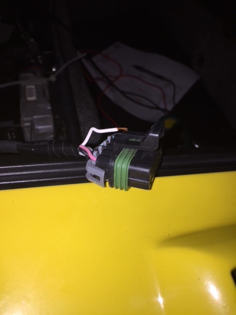
This is now the second wire that has broke free of its terminal on it's own, with no user error. This is a shame, considering the extremely expensive cost paid for my harness.
I have not re-pinned Pin G (White wire) yet but it does pass a test light test on the exposed wire itself. I am certain that this was at least part of the culprit, if not the entire cause of the cruise control not working.
Continuing on...
darbysan had mentioned that I need to be sure that the Cruise Inhibit signal wire Pin H (which in my case is Black and not DK Green) is also attached to Ground at all times. I tested it for continuity to ground and got a beep from the multimeter. The resistance test was as follows:
Pin H Resistance: Black wire (Not Green) 001.5 – 002.5 ohms. The reading bounced around no matter the grounding point used.
I have therefore concluded that my Inhibit is "grounded" rather than "open".
darbysan had also shared "that some modules need to see the Cruise Inhibit wire to ground, while others preferred it to be left open. If it goes to ground, then pulling the pin and leaving it out would be a good test. If it's not going to ground, then try grounding that wire and see if it helps."
"I don't know how your harness was built, but it will be either "grounded" or "open". Whichever way, you would want to try the other possibility as a test."
I plan to do this test if re-pinning Pin G (White wire) does not solve the problem with the cruise control working properly.
Additional testing of Pin F for continuity to ground yielded a beep on the multimeter. The resistance test was as follows:
Resistance Pin F: 017.5 – 018.1 ohms.
Many thanks to both Paul and Mike! Without your expertise, guidance and patience, I could not have gotten this far in my testing and diagnosis. I really appreciate this help and it is people like you guys that make this forum the special place that it is!
-Van[This message has been edited by VanGTP5000 (edited 03-21-2018).]
|
|
|
|
VanGTP5000
|
MAR 22, 11:40 AM
|
|
Ok so my cruise control still doesn't work!
After re-pinning Pin G (White wire) I was successful in pulling yet another wire out of the harness plug with virtual ease  . This time it was Pin A (Gray wire). I went back and I now have all of the wires secured to their terminals in the plug but the cruise control still does not function. . This time it was Pin A (Gray wire). I went back and I now have all of the wires secured to their terminals in the plug but the cruise control still does not function.
I had initially planned to employ darbysan's test of pulling the Cruise Inhibit signal wire Pin H from the plug as a test to see if leaving it "open" would solve my problem. However, after struggling with three of the wires pulling out of their crimped terminals, I am very hesitant to attempt removal of Pin H from the plug. Especially given it's location right in the middle of the harness plug. Attempting to pull this Pin would almost certainly cause other wires to become dislodged again. I am sure a more skilled individual could accomplish this task better than my clumsy ass.
Having said that, I am thinking about just purchasing yet another digital cruise servo instead. With the thinking that the 96-99 Cadillac Northstar units Ryan mentioned earlier in this thread may solve the problem. After all fieroguru did mention 3rd unit is the charm  . Apparently, Ryan has found much more success with these units (whether "open" or "grounded" Inhibit signal wires) vs. other similar servo units used in this application. . Apparently, Ryan has found much more success with these units (whether "open" or "grounded" Inhibit signal wires) vs. other similar servo units used in this application.
What do you guys think? I would also appreciate any interpretation of the resistance numbers I posted earlier. Are they even in the ballpark?
Thanks,
-Van
|
|
|
|