
 
     |
| Rebuilt and Installed a 3.4PR (Page 1/7) |

|
ManMadeChickens
|
MAY 01, 02:44 AM
|
|
Hello all. Here's the backstory here: I have a 1986 SE V6 that started developing a lower-end knock at 149,900 miles. I set out to find a cheap way to build up some more power while replacing the failing 2.8. Luckily, my good friend Damian (thedrue on PFF) had a 3.4L longblock on an engine stand that he was willing to let me use. It came out of a wrecked Camaro, and supposedly had something like 160,000 miles on it. I set out to rebuild this engine, build it up a little bit more powerful than stock, and install it in place of my 2.8. He and I tore it down to a shortblock, and I took all the parts back to my garage to start in on the endeavor.
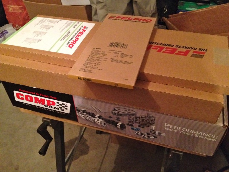
Fel-Pro gaskets, Comp Cams valve train and timing kit.
A good way to start in on some fun. :-)

Rodney Dickman 3.4L starter relocation jig. Duplicates the starter location to the other side of the block for transverse applications, like the Fiero.
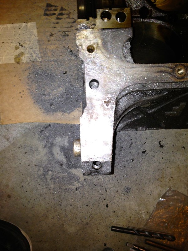
Drilled, counterbored, tapped and tested. This jig is seriously worth the money. Lines it up flawlessly, and drills and taps the holes perfect. I'm very glad I chose to buy it.

Replacing the valve seals, retainers, spring buckets, and adding double valve springs.
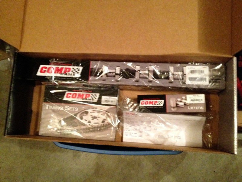
New CompCams 260H camshaft, lifters and timing chain/sprocket.[This message has been edited by ManMadeChickens (edited 03-18-2014).]
|
|

|
ManMadeChickens
|
MAY 01, 02:51 AM
|
|
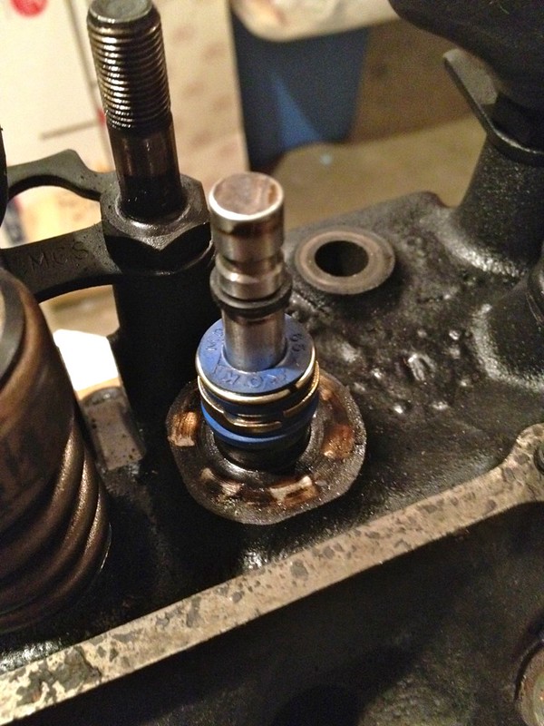
Intake valves get these new bright blue valve guide seals. All valves get the plain-Jane black o-ring.

Head one of two "complete" as far as hardware goes. New double valve springs, valve guide seals, valve stem o-rings, retainers, locks, and a thorough cleaning. The other head got the same treatment.
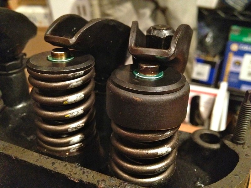
Up-close shot of the valve springs, and new bits. You can see though the main coils to the additional inner spring, which significantly increases the tension against the valve to close it. All the exhaust valve springs have those funny buckets on the top of them (right). For some reason, my new retainers were too big to fit in the standard opening. GM put the buckets there for a reason, so I had to bore out the opening to get the new retainers to fit the stock buckets. Not a big deal, just an extra step I didn't anticipate.

One of three broken studs stuck in the head. The machine shop handling my work was able to drill these out and put inserts in their place.
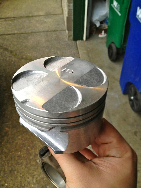
"Flat Top" 3.4 DOHC pistons attached to the 3.4 Pushrod connecting rods. Should be right about 10:1 compression. This was one of the upgrades I talked about earlier. These pistons share all the important dimensions with the 3.4PR pistons, but don't have the dish, so it raises the compression. These cost about 1/4 as much as a custom set of truely flat topped 3.4L bore pistons.[This message has been edited by ManMadeChickens (edited 03-18-2014).]
|
|

|
ManMadeChickens
|
MAY 01, 02:59 AM
|
|
|

|
ManMadeChickens
|
MAY 01, 03:06 AM
|
|
|

|
ManMadeChickens
|
MAY 01, 03:19 AM
|
|
|

|
ManMadeChickens
|
MAY 01, 03:28 AM
|
|

Both heads installed. The 60 bank-angle design is clearly visible here. Rather than mess with trying to remove the odd-sized plug to put the temperature sender in, I simply swapped heads side to side. They're symmetrical, so no harm no foul if you already have them off.
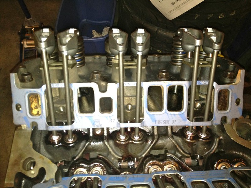
Lower intake manifold gasket installed, pushrods installed, and new CompCams Magnum 1.52 roller-tipped rockers installed. I contemplated going with 1.6 ratio, but I wasn't sure if I was going to have valve clearance issues with my 3.4 DOHC pistons. This cam has bigger lift than a stock cam already anyhow.

A good view of the lifters, pushrods, and roller-tipped rockers. All these parts are new. The pushrods are reinforced, which helps get all the camshaft's lift to the valve. Solid rockers rather than stamped, again to reduce flex and loss of lift. Roller tips reduce friction and wear. They do produce a bit more valvetrain noise however.

A West Coast Fieros cam position sensor delete plug. The Camaro that this engine came from uses a cam position sensor for an input to the engine computer. The Fiero engine computer does not need this sensor, so a plug is installed in it's place. It probably would have stayed put alright, but I threw in a bolt over it in the mounting hole just in case.
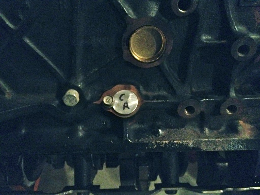
Similar situation on the side of the block- this is a WCF crank position sensor delete plug.[This message has been edited by ManMadeChickens (edited 03-18-2014).]
|
|

|
ManMadeChickens
|
MAY 01, 03:42 AM
|
|

When it's 2am, and you don't have a "crank sprocket installation tool," you improvise. In this case, I was able to get the crank sprocket pressed on using the harmonic balancer bolt and a pair of deep sockets to take up the depth. It worked flawlessly. I rock.
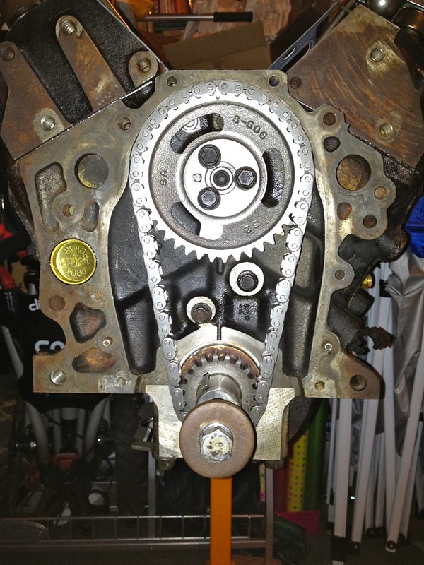
Crank sprocket installed, cam sprocket installed, and timing chain in place. The old chain damper was so gouged and chipped that I ordered a replacement. It didn't go on until later.
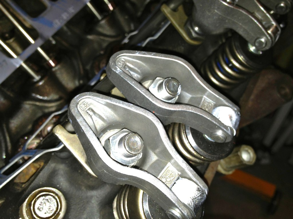
Valve lash adjusted. The roller-tipped rockers are a stock 1.52:1 ratio. However, they're cast instead of stamped, which makes them much stronger. Keeps them from deforming with my high lift cam, and stiff double valve springs. There was a lot of discrepancy about how much to crank down the nut after zero lash. Each CompCams pamphlet that came with parts (cam, lifters, rockers) had a different value ranging from 1/2 turn to 1.5 turn after zero lash. The factory service manual procedure says 1.5, and a Fiero club website I found detailed the process and mathematically showed that 1.5 is ideal, based on the thread pitch of the stud, the lifter height, and nominal preload amount. So I decided that 1.5 was what I wanted. Seems to work just fine.

Bought a junkyard gear reduction starter. Cleaned it up so it could make it's way onto this engine. The gear reduction starter is physically smaller in most dimensions, weighs less, takes less energy to crank, and cranks faster. Overall just a much better part! Check out the photo below for comparison to a stock unit.
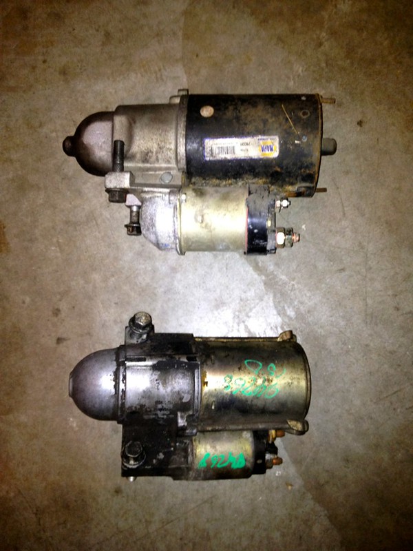
As mentioned above, the gear reduction starter is smaller diameter, shorter, lighter, and better in pretty much every way. With my new engine being fresh and tight, and the new 10:1 compression, I felt it would be a good idea to put this on.[This message has been edited by ManMadeChickens (edited 03-18-2014).]
|
|

|
ManMadeChickens
|
MAY 01, 03:57 AM
|
|
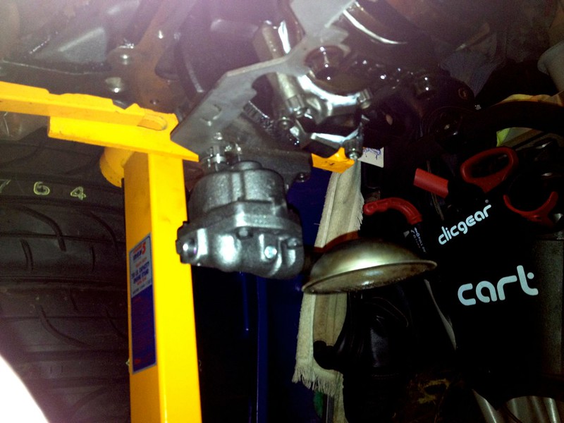
This is a terrible photo, but the point is that the oil pump, and pickup are on. I found an extra oil pump drive amongst my random Fiero parts, and threw it in. This is a Melling stock replacement pump, with the standard 3.4 pickup tube. I tack welded the pickup to the pump, so there's no chance of it falling out.

Starting to tear down the top end of my original engine. In this shot, I've already undone the air intake hose, the clutch slave, shift cables, taken out the distributor, and undid a great many vacuum hoses. Bolts for the upper intake manifold are just sitting in place.

Upper intake manifold removed. Not exactly sure how oil got into the dummy port positions on the middle intake manifold, when the gasket covers them... but it's there, and doesn't appear to have hurt anything.
Next I removed the fuel rail, and injectors. Taking out the Lower Intake Manifold requires removing the valve covers, which is kind of hard to do with the engine dogbone bracket in place. I waited to do it when it's more accessable with the engine out of the car.
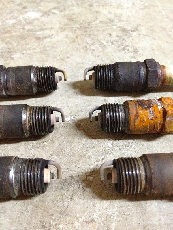
The old plugs were just right. Only car people will understand how cool it is to pull 30,000 mile plugs out, and see they're all perfect tan color, no oil contamination, and see them all wearing evenly and correctly. It's a shame how good this engine ran, it's knocking rod bearing excluded. The middle one on the right is the one that gets water dumped on it every time the deck lid is opened when it's raining. Pretty obvious, really.
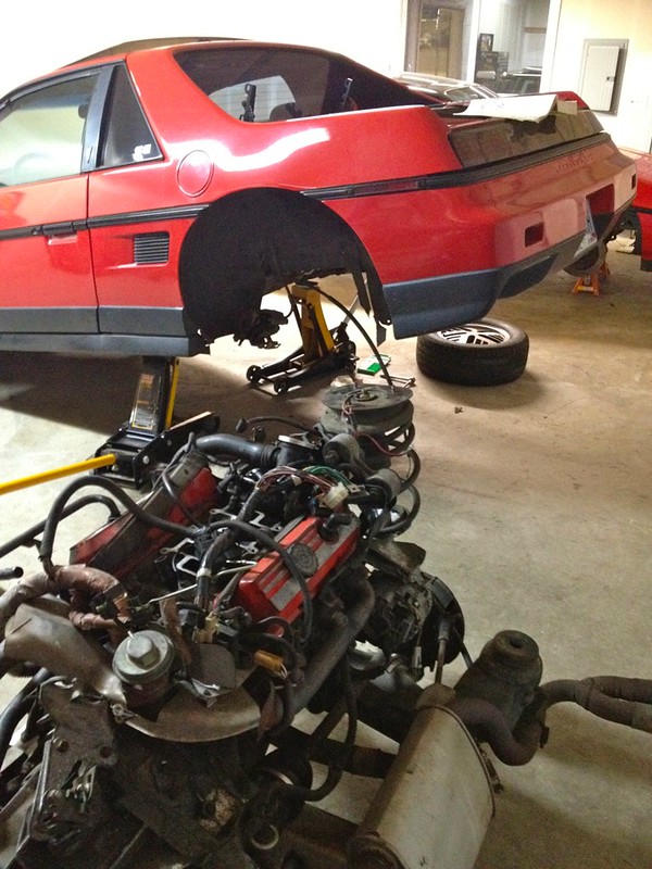
Success! It's always a good time when you get a cradle out in a couple hours, first try, no snags.[This message has been edited by ManMadeChickens (edited 03-18-2014).]
|
|

|
ManMadeChickens
|
MAY 01, 04:07 AM
|
|

Valve cover removed on the old engine. Everything is oil-stained, but otherwise normal. I'm very pleased that after 150,000 miles there's no sludge or grime. Makes my regular maintenance seem worth it that much more after getting to see the benefit first hand.
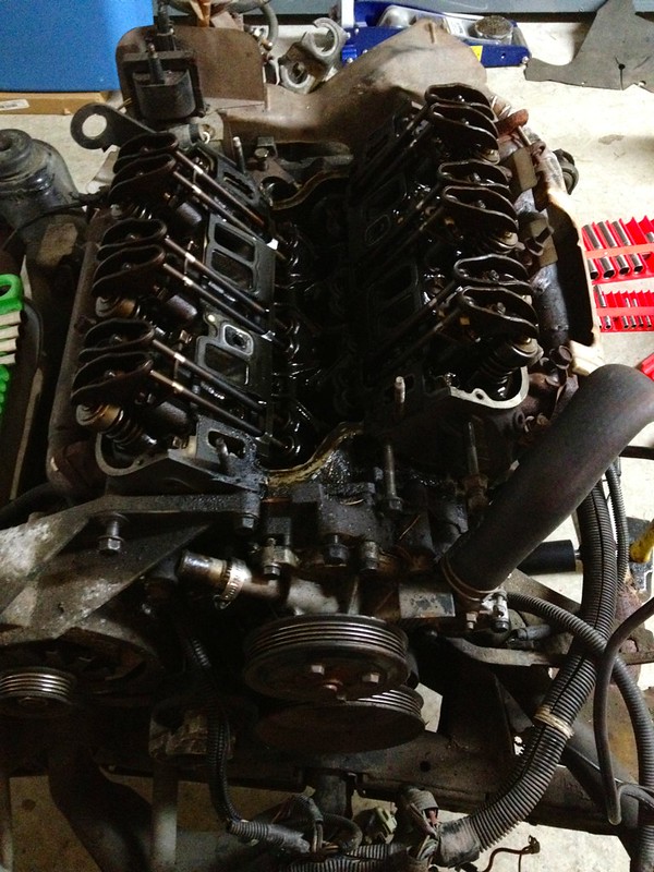
Pilfering the old engine for external pieces to go onto the new one. Already removed the lower intake manifold, dog bone bracket, A/C bracket, oil pressure gauge sender, valve covers, and more.

Cleaned up and installed the lower intake manifold. I RTV'd the gap between the heads and manifold, and torqued to spec.
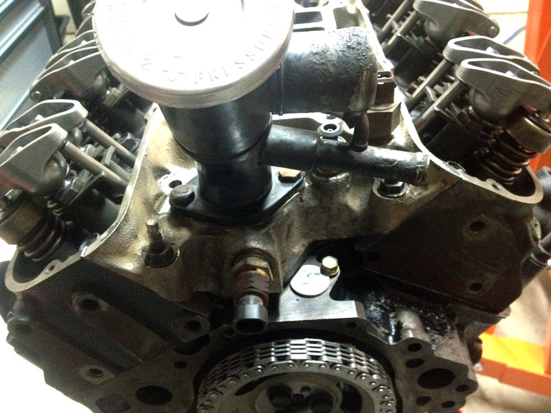
LIM installed, I again used RTV along the exposed block edge. It's now pretty clear why there's a flat side cut into the cam position sensor plug.

Valve covers cleaned up and reinstalled, it's looking a lot like a Fiero engine now![This message has been edited by ManMadeChickens (edited 03-18-2014).]
|
|

|
ManMadeChickens
|
MAY 01, 04:16 AM
|
|
|
    
  |
|
