 
     |
| AR electronic cruise control wiring question (Page 1/5) |

|
Curtisk1060
|
SEP 10, 01:17 PM
|
|
|
I'm in the process of building my harness for my 3800SC swap into my 88GT and I have the prints, etc. from Ryan for the electronic cruise control portion of the swap. Here is my question which I know many of you have already done. Do I need to run the two wires from C1-72 (dk grn cruise inhibit control) and C2-59 (wht cruise control status) from my PCM to the rear compartment location of the existing OE servo connection or is there another place internally of the car to splice into? I cannot determine this from my service manual. Also how many have done this conversion to stock vehicles vs. just during engine swaps?
|
|
|
|
FIEROFLYER
|
SEP 10, 02:20 PM
|
|
|
Only connection to the PCM for the newer cruise with a 3800 swap is the VSS out put to feed it. Dan
|
|
|
|
phonedawgz
|
SEP 10, 04:29 PM
|
|
It depends.
Yes you need the 4000 PPM output to be bridged to both the speedo (high) and the cruise input for automatic transmission or later model manual transmission applications. The 4000 PPM output needs to run through a speedo buffer http://www.reddevilriver.com/Related_Products.html
For a Fiero manual transmission you can run the VSS to both the speedo and PCM. Then the only thing connected to the 4000 PPM output goes to the cruise control.
You can run the cruise inhibit lead to the PCM if you wish to. You can also just ground it. The idea of the cruise inhibit is so the PCM can enable and disable the cruise depending on speed and conditions. If you run the lead to the PCM then also make sure your PCM is properly programmed for the correct 4000 PPM (ish) input. The stock AT VSS or later model MTs have a 24000 PPM output.
You need both brake inputs for the cruise control to work. One (C) needs to be +12 at idle, and the other (G) needs to be +12v with the brake applied. You can not hotwire these inputs because the cruise looks for them to change states at least once before it will start to function.
You can use the cruise engaged output to light a light on your dash if you wish.
|
|
|
|
Darth Fiero
|
SEP 11, 02:15 AM
|
|
I have had some issues with some of the GM electromotive cruise control units (even those marked "AR") in Fiero swaps not wanting to engage at all. This is when they are NOT connected to the PCM on the cruise inhibit and status circuits.
I believe the problem is some of these cruise control modules want to see the cruise inhibit input change state at a certain speed (perhaps?) and that won't happen if you just ground that wire.
If you are using a manual transmission in your swap, the PCM may never ground the cruise inhibit wire to enable cruise operation because there is no electronic auto transmission present.
Since the discovery of this problem, I have been building my stockpile of 96-99 Cadillac Northstar cruise control modules (they look identical to the ones used on the 3800s; except the Cadillac ones are marked "V8"). Every single 96-99 Northstar cruise control module I've gotten from a Cadillac has worked fine without having the cruise inhibit and status wires hooked up to the PCM. All you'll need to do is permanently ground the cruise inhibit input to the cruise module.
Cables can be easily swapped out on these cruise modules so you can use any cable you need to match your throttle body.
-ryan------------------
OVERKILL IS UNDERRATED
Custom GM OBD1 & OBD2 Tuning | Engine Conversions & more | www.gmtuners.com
|
|
|
|
olchap
|
SEP 11, 10:43 PM
|
|
|
|
|
Fierotregg
|
OCT 20, 08:36 AM
|
|
|
I'm having this problem with my 3800 swap with the AR cruise control module, it won't work at all, have tried 2 different "AR" modules. I get nothing when trying to set the cruise at any speed.
|
|
|
|
phonedawgz
|
OCT 20, 06:08 PM
|
|
Gray – You should have voltage on the gray wire anytime the cruise control switch is in the on position
Dark Blue – You should have voltage on the Dk. Blue wire when the set button is depressed
Gray/Black – You should have voltage on the Gray/Black wire when the Resume/Accelerate button is depressed.
Brown/White – You should have voltage on the Brown/White wire when the cruise control is turned on. The voltage should drop to zero when the brake or clutch pedal is depressed. If not check the brake/clutch switches.
If you have no voltages on any of the wires, check the clutch and brake pedal switches with the yellow wires on them. With both pedals (or one if auto) the switches should be depressed and +12 should be present on both sides of the switch (key on).
Pink - You should have +12v on the Pink wire when the key is on.
White or Lt. Blue wire – Connects to either the White or the Lt. Blue wire at the brake switch. This wire should have power on it whenever the brake pedal is depressed.
|
|
|
|
VanGTP5000
|
FEB 10, 12:04 AM
|
|
| quote | Originally posted by phonedawgz:
Pink - You should have +12v on the Pink wire when the key is on.
White or Lt. Blue wire – Connects to either the White or the Lt. Blue wire at the brake switch. This wire should have power on it whenever the brake pedal is depressed. |
|
Anybody know where this 3 plug connector is located? I don't see it at my brake switch.
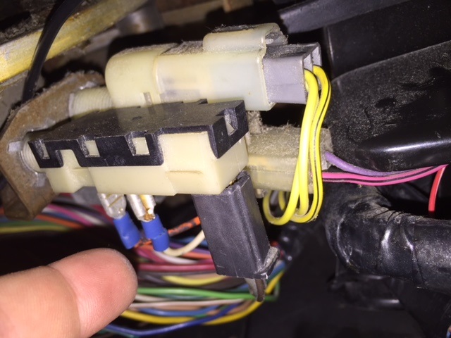
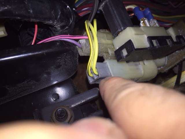
I am supposed to be seeing this right? This pic shows the Lt Blue, White, and Pink wire:
Please help me locate it.
-Van
|
|
|
|
phonedawgz
|
FEB 10, 02:06 PM
|
|
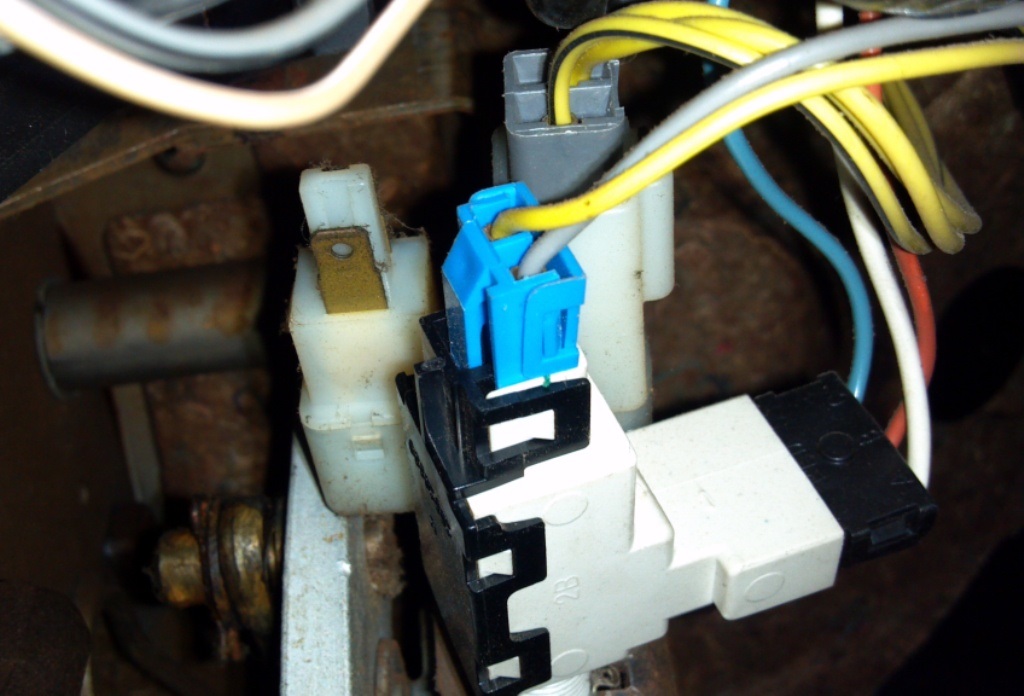
Take a 12v test light and connect it to ground and put the probe on the white wire shown in your pic. That would be next to the orange wire. The white wire I am looking at in your pic has a slide on terminal crimped on it. It looks like someone made some mods to your brake switch, but the white wire should be the one you are looking for. You will know it's right if you get voltage on it when, and only when the brake pedal is depressed. I think you will find you have power all the time on the orange wire.
If you have power on the white wire when it is depressed, then it is the right one.
|
|
|
|
VanGTP5000
|
FEB 10, 02:12 PM
|
|
| quote | Originally posted by phonedawgz:
Take a 12v test light and connect it to ground and put the probe on the white wire shown in your pic. That would be next to the orange wire. The white wire I am looking at in your pic has a slide on terminal crimped on it. It looks like someone made some mods to your brake switch, but the white wire should be the one you are looking for. You will know it's right if you get voltage on it when, and only when the brake pedal is depressed. I think you will find you have power all the time on the orange wire.
If you have power on the white wire when it is depressed, then it is the right one. |
|
Thank you Tim! In your email you mentioned that I was supposed to look for a white wire next to Pink (not orange) and Lt. Blue like in the picture...that's why I wasn't sure if I was pointing to the right connector in my pic.
-Thanks for clearing that up.
-Van
|
|
|
