 
     |
| 84 fieor-- 94 N* swap (Page 1/24) |

|
mcfrandon
|
NOV 18, 12:58 AM
|
|
Alright this is my first time posting here on the forum. I'm a new member. I have been lurking for some time now, reading up on the northstar swaps and gathering any good info i can find. The best info i have found cam from a member who's name was something like Ajaxman or somethiing close. He posted several diagrams for the early northstar
(1993 obd1) which have been a great help for me. The engine I have is out of the 1994 ETC model. The ECU pinouts seem to be correct even tho the wires are different colors which is not a big deal im sure. I am getting stuck on a few things tho and im pretty sure I could figure them out but i would like some reassurance.
On the oil pressure sending unit I have a 4 wire pigtail coming from it instead of 2 like all the others i have seen. That is the one that came on the engine when i pulled it.
I was thinking the spec stage 2+ clutch would be enough because it says its rated to over 400 ftlbs of tq, but it looks like most people are using the stage 3+??
As far as I have investigated it sounds like this year pcm has different processors for the engine and transmission, so the engine should run without the tranny/speed wiring?
On ajaxmans post for his 93 he posted that the fuel enable pin for the ECU coming from the pass key system might work with 2.5v? I dont want to run any sort of VATS or passkey. What voltage can I run to the fuel enable input to allow the engine to run? And i would just leave the starter inhibit output disconnected.
I haven't been able to get ahold of any forum members or companies who mess with these computers. Who is my best bet?
I will continue to search. I hope to add some pics soon but the system on this thread is different then i'm used to so i will follow the instructions and get it going as soon as possible. thanks guys
|
|
|
|
jb1
|
NOV 18, 02:37 AM
|
|
you only need two wires for the oil pressure, maybe just one (id have to look at mine , i believe it is only 1 wire) the others if for fuel pump relay and cuts the fuel when the oil pressure drops.
No idea on the trans wiring or clutch , I run the 4t80e .
As far as the passkey , I have mine wired up with the caddy key cylinder in a hidden location and just pull the key when in storage, have thought about eliminating it and using a resistor relay and push button..
------------------
87GTseries 1 3800sc (7.597 @88.53 1.579 60ft)
(series II swap in progress)
85GT Northstar/ 4t80e
86GT 3800 n/a---sold
Northstar Rebuild
|
|
|
|
IXSLR8
|
NOV 18, 02:45 AM
|
|
A little more information about your Northstar Fiero configuration would help us.
Based on what you have said, you have an early 1994 Eldorado with an OBD1 computer and you are planning to run it with a manual fiero transmission. Is that correct? Or are you running the newer 6 speed G6 tranny?
You want to know what clutch to use, how to defeat the pass key/security, and if you can run the engine without the automatic transmission VSS? Is that correct?
The N* will run on a variety of computers and the stock computers can be altered based on your running configuration of choice.
|
|
|
|
mcfrandon
|
NOV 18, 04:13 AM
|
|
OF course I already spelled Fiero wrong in the title. crap.
| quote | Originally posted by IXSLR8:
A little more information about your Northstar Fiero configuration would help us.
Based on what you have said, you have an early 1994 Eldorado with an OBD1 computer and you are planning to run it with a manual fiero transmission. Is that correct? Or are you running the newer 6 speed G6 tranny?
You want to know what clutch to use, how to defeat the pass key/security, and if you can run the engine without the automatic transmission VSS? Is that correct?
The N* will run on a variety of computers and the stock computers can be altered based on your running configuration of choice.
|
|
Correct you are right on track. The 5sp fiero transmission. Its not the getrag and i know it will have shift cable location issues and its not as strong but it's what im going to start with.
I would like to run the stock computer. The engine/trans is already in the car with the subframe modified of course, and the engine bay as well. I also have the corvette fuel pump in the tank already and already used the factory fiero harness to crank the starter. Im waiting to buy the flywheel/clutch till I actually here this thing fire.
yes I would like to know how to get around the passkey. I had no idea of it when i pulled the engine/computer so it is long gone. It looks like when the passkey is activated it sends a signal voltage to the ecu to allow fuel flow. AJxtcman says here that the voltage required to allow the ECU to fuel could be 2.5v but it was never verified... does anyone know if this is true?
6th post down he said: 2C8 - PASS-Key decoder Fuel enable input. 2.5V? or Run it to A3 of the PK module.
http://www.fiero.nl/forum/A...090219-2-080147.html
Ok so I can just run the 2 wires on the oil sender then.... I have yet to see the sender with 4 wires like mine in any diagram or picture. weird. Also I dont have a diagram for the EVAP solenoid. its only 2 wires though. one wire goes to the ecu but im not sure if the other is 5v return 5v reference or just a ground. I think i'm making this more complicated than it is haha.
|
|
|
|
phonedawgz
|
NOV 18, 06:06 AM
|
|
Typical oil pressure sender wiring - add a 4th pin (the one missing) as ground. I usually run all the wires to the oil pressure switch thus making the oil pressure switch a back up to the fuel pump relay.
Different color wires at the PCM than your pin out are a red flag. GM uses a fairly standard color set for it's sensors. The EGR is one place however that it seems to fail on this.

Passkey requires a signal, not just a voltage. Run this to the PCM passkey input. Yes drop the starter inhibit relay from the wiring.
http://www.ebay.com/itm/GM-...em4186510605&vxp=mtr
The other end of your EVAP Solenoid goes to switched power. Most (not all) Pink wires go to +12v switched.
Gray +5v is generated in the PCM and is only used for sensors. Solenoids and relays run off of +12v. On almost all the PCM grounds the device to turn it on. The exception to this is the fuel pump relay. On the fuel pump relay the PCM sends out +12 v on the Dk. Green/White wire and the other end of the fuel pump relay coil needs to be grounded.
The PCM NEEDS a VSS input. Most PCMs will run the engine at a high idle without it. The PCM needs to know when IT should be adjusting idle (throttle closed and vehicle stopped) and when it should not be adjusting idle (throttle closed and coasting down a long incline). You can T wire the VSS output of the transmission to both the PCM and speedo. Note - sometimes the PCMs ground the VSS differently than the speedo. If after hooking it up you get no speedo and scanning the PCM shows no vehicle speed, reverse the two wires to the PCM and try again.
Try Ryan Gick - sp1@gmtuners to see if he can program the PCM.
Many late OBD1 PCMs look for a load on the devices it controls. Most OBD2 pcms do also. You may get trouble codes that turn on the MIL light, and may also reduce power without the electrical loads the transmission would produce.
|
|
|
|
mcfrandon
|
NOV 18, 01:36 PM
|
|
ok I ordered that bypass and that was what I was looking for all along but it seemed like the ones I cam across still needed to the passkey module. -thank you.
So when I go to wire that will I use the 30 or 50hz or have a switch to switch between the 2?
I will attach the oil sender diagram I have with the wire colors I have. Also will attach some of the diagrams from AJxtcman's post with my changes to some wire colors/terminal labels. The wires all seem to end up at the same pin and match up to the correct sensor or module, so I assume they are correct.. You'll have to look close to see what I have written down as different colored wires or terminal letter labels. I guess the wire I have labeled brown is more of a tan and it looks like it may of had a black line on it but not sure. But i assume it has the same purpose as the one on the diagram of course. I have the grey wire(d) from the sender going to pin 1b13 (fuel pump feedback) which also ties into the fuel pump relay. I think the pink(c) must be switched 12v? blk/wht(b) obviously to ground. So does that leave pin a on my diagram to go to the oil pressure gauge/light?


On my evap solenoid I have a Green/yellow wire and a tan wire. The green/yellow looks like green/white now maybe from age/oil haha, but it does go to ecu pin 3E12 (evap solenoid control). So you think the tan wire should go to switched 12+? maybe its really faded pink.
On the VSS I will need to create some circuit to convert it to what the PCM needs correct? I have seen it floating around here it looks like it can be built from radio shack with resistors and such right?
I tried gmtuners with no reply yet. Matthew Howell with Howell Engine Developmentes got back to me and said they can delete the transmission codes and such.
|
|
|
|
mcfrandon
|
NOV 18, 01:49 PM
|
|
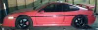
here are some pics of what im working with here just to have a visual. My build is kinda grungy compared to most of the ones I've seen here all cleaned up nice and such haha.
Also if anyone has a recommendation or link for a good firewall insulation/heat mat (im not sure what the actual name is) it would be helpful!


PCM


|
|
|
|
phonedawgz
|
NOV 19, 12:02 AM
|
|
VATs bypass - You will have to see which frequency works with your PCM. Once you do that then just hard wire it.
Oil Pressure Sender - Yes pin A - Tan/Black - goes to C203 E - Oil Pressure Gauge/light. If your 84 has an oil pressure light only, then make sure to use an oil pressure sender for a light.
Evap solenoid - Yeah sometimes they used Dk. Green/Yellow instead of Dk. Green/White. The other wire is indeed Pink. Yes it runs to +12 switched.
I sell the circuit if you want to purchase it, or yes you can make it for less - http://www.reddevilriver.com/Related_Products.html - or http://www.gmtuners.com/swap/3800.htm
You did catch that the 84 C203 and C500 wire different than the 85+ that is commonly shown correct?
Locate the computer in the console - that one is not weatherproof.
|
|
|
|
mcfrandon
|
NOV 20, 01:13 AM
|
|
So it sounds like I won't be able to use this sender except for what the pcm needs or I am not sure if it would throw a code.. Should of kept the one off the fiero engine to install into one of the oil cooler ports that will be plugged.
So let me get this straight... the VSS on the fiero 5 spd can be wired straight to the N* pcm hi and lo speed sensor input? But I will need to use the speedo conversion to go from the ECU to the c203?
The C203 is the 2 smaller plugs under the console. The C500 is the big plug that connects the body wiring to power right? the c500 is in my last picture i think. I didn't know they were different but thanks for the heads up! I have yet to look at or come across any of the diagrams for either of these connectors, however i will need to very soon.
|
|
|
|
phonedawgz
|
NOV 20, 04:36 AM
|
|
Usually the A - B portion of the oil pressure sender wires only to the oil pressure light / gauge. Usually the C - D portion of the oil pressure sender is only used as a back up to the fuel pump relay. So none of the oil pressure sender pins usually connect to the PCM.
The Purple and Yellow wires are tagged High and Low referring to their electrical properties. That is one is ground and one is signal. They are not a high speed and low speed wire however. Yes the Fiero VSS should be able to provide a signal input to your PCM.
Yes you have the locations correct.
84 C203 & C500 http://www.fiero.nl/forum/Forum2/HTML/121625.html
Also when building an 84 harness I use a relay controlled by the pink ECM power wire to activate two more fused power circuits - one for the injectors and one for the other engine/transmission power requirements other than the MAF. I put the MAF on the pink wire that runs to the ECM and now also runs to this relay.
Fuse the injectors at 10A. Fuse the second circuit at 20A.
The ignition power wire on C500 I use for ignition power. I install a fuse at C500 (20A) since GM failed to fuse that circuit in the Fiero.[This message has been edited by phonedawgz (edited 11-20-2014).]
|
|
|
