 
     |
| Instrument Panel Lights/ Illumination Voltage (Page 1/1) |

|
Pyrostatic
|
JUL 27, 08:37 PM
|
|
Hello,
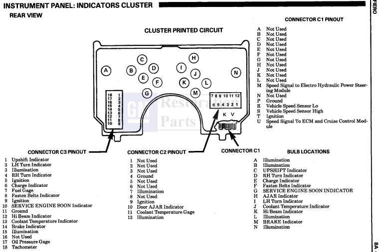
The voltage for the "Illumination" wires for connectors C2 and C3 into the Instrument Panel are putting out about .6 to .8 volts. How can I increase this to 12 volts?
I have installed a different dash into my car and it requires 12 volts to light the new instrument panel.
Thank-you
|
|
|
|
theogre
|
JUL 27, 11:17 PM
|
|
Jump the transistor.
See my Cave, Dash Dimmer "to test"------------------
Dr. Ian Malcolm: Yeah, but your scientists were so preoccupied with whether or not they could, they didn't stop to think if they should.
(Jurassic Park)
The Ogre's Fiero Cave
|
|
|
|
Pyrostatic
|
JUL 28, 09:32 AM
|
|
Awesome thanks Ogre!
I was sitting in bed last night with Fieros on the brain and unable to sleep. I was thinking about checking the voltage in the headlight/ fog light switch and the dimmer switch and seeing where the power goes (and how much) when the switch was turned on. I was hoping it was 12v. I had read not to put full voltage to the transistor so I figured I'd cut that out.
When I read your post this morning it took all the guess work out though! 
I had read your post yesterday too, but my brain couldn't put it all together.
I cut out the transistor and the dimmer like you said and it worked great. I blew two fuses. It took me a bit to figure it out but I think the power wire for the lights for the oil pressure/ battery gauges was touching on the metal of the stereo. Once they were moved out of the way I didn't have any problems. Anyways, thank-you so much!
Do you have any advice on how I can ground a bunch of electrical wires at the same time? I have the ignition power wires grounded properly through the new connectors, but individual pins/ wires need to be grounded also.
Can I just run one ground (original C1 ground) and splice it/ tie it in with multiple wires? If so what kind of connector could I use for that? I'd rather not run 6+ individual grounds.
Thank-you.
|
|
|
|
theogre
|
JUL 28, 02:39 PM
|
|
| quote | Originally posted by Pyrostatic:
Do you have any advice on how I can ground a bunch of electrical wires at the same time? I have the ignition power wires grounded properly through the new connectors, but individual pins/ wires need to be grounded also.
Can I just run one ground (original C1 ground) and splice it/ tie it in with multiple wires? If so what kind of connector could I use for that? I'd rather not run 6+ individual grounds. |
|
Depends just what a wire grounds a thing...
Very Small lights and gauge can splice to C1 and C2 grounds. Think "C3" for OE speedo has ground too.
If whatever draws 5+A then likely should have own ground to frame somewhere.
Example...
GM used G201 and G202 to ground a lot of things in the cabin and dash including the cig lighter and Fuel Pump to make car easier to build but often causes problem and worse for high draw items like lighter and FP. Just those eat 6 to 9A each.
At minimum you should clean/fix both ground lugs and "frame" to bright metal and coat w/ brake or silicone grease so FP gets a good ground.
PW and few others have own ground on low P-side A pillar. Many whining PW is slow never check the power or ground yet still buying whatever to speed up PW.
See my Cave, Wire Service and maybe Electric Motors. Motors hate iffy power/grounds but many other things will have same problems but not so obvious.
|
|
|
|
Pyrostatic
|
JUL 29, 11:31 PM
|
|
Thanks Ogre for your informative reply.
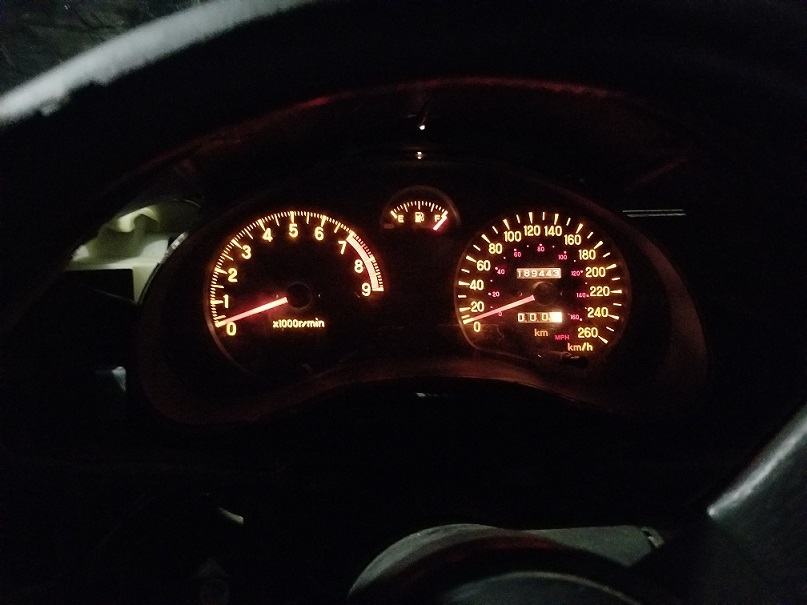
Yeah, sorry I just meant grounding some gauges and indicator lights for now. I went and got a terminal block for connecting them all, might be overkill, but it's working good. I took your advice and picked up some dielectric grease. I used the G201 ground point you mentioned for this new ground and cleaned the metal good. (I'll put up a picture of the dash you helped me light up! )
I never thought about that for the power windows, mine are very slow. I'll definitely clean the G301 ground another day and see if that helps. They are working, so maybe I'll just focus on stuff I'm in the middle of for now.
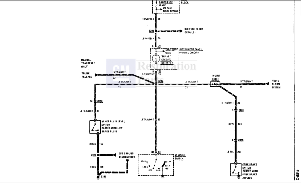
So today I was trying to figure out the parking brake circuit. I want the "Brake Indicator" wire C3-14 to put out 12 volts to power the indicator on the instrument cluster (not a Fiero cluster).
I read the circuit and located a purple wire coming out of the parking brake (see attached diagram). I followed the wire and saw it go through the two connectors and then turn to the different colour. I took my voltmeter to it between the parking brake and the first connector and got 0 volts. I took a reading on that C3-14 wire and it was .1 volts with the purple wire connected and .3 volts with the wire cut. I'm very confused.
(My "Buzzer" is currently removed as it was driving me nuts months ago, maybe I should have tried checking with that installed)
(Also there was a second larger gauge purple wire running with the smaller one, I was playing with the smaller one)
Any advice?
|
|
|
|
theogre
|
JUL 30, 04:01 AM
|
|
OE brake light is on when P-brake or B-fail switch next to MC is on and grounded.
IOW 12v-bulb-switch-ground
Mod dash needs 12V for Brake Light?
IOW 12v-switch-bulb-ground?
Likely easiest w/ small relay.
12v "Hot w/ Key in Run" (Same as OE on Gauge fuse) to coil and main contact.
P-brake etc to other coil term.
Mod dash to N.O. contact.
PB or B-fail switch on then relay is on and relay turn to idiot light.
Could to it other ways but small relay is cheap and simple.
|
|
|
|
Pyrostatic
|
AUG 04, 10:00 PM
|
|
Thanks Ogre.
I just did some research on relays. I'm still a little confused...
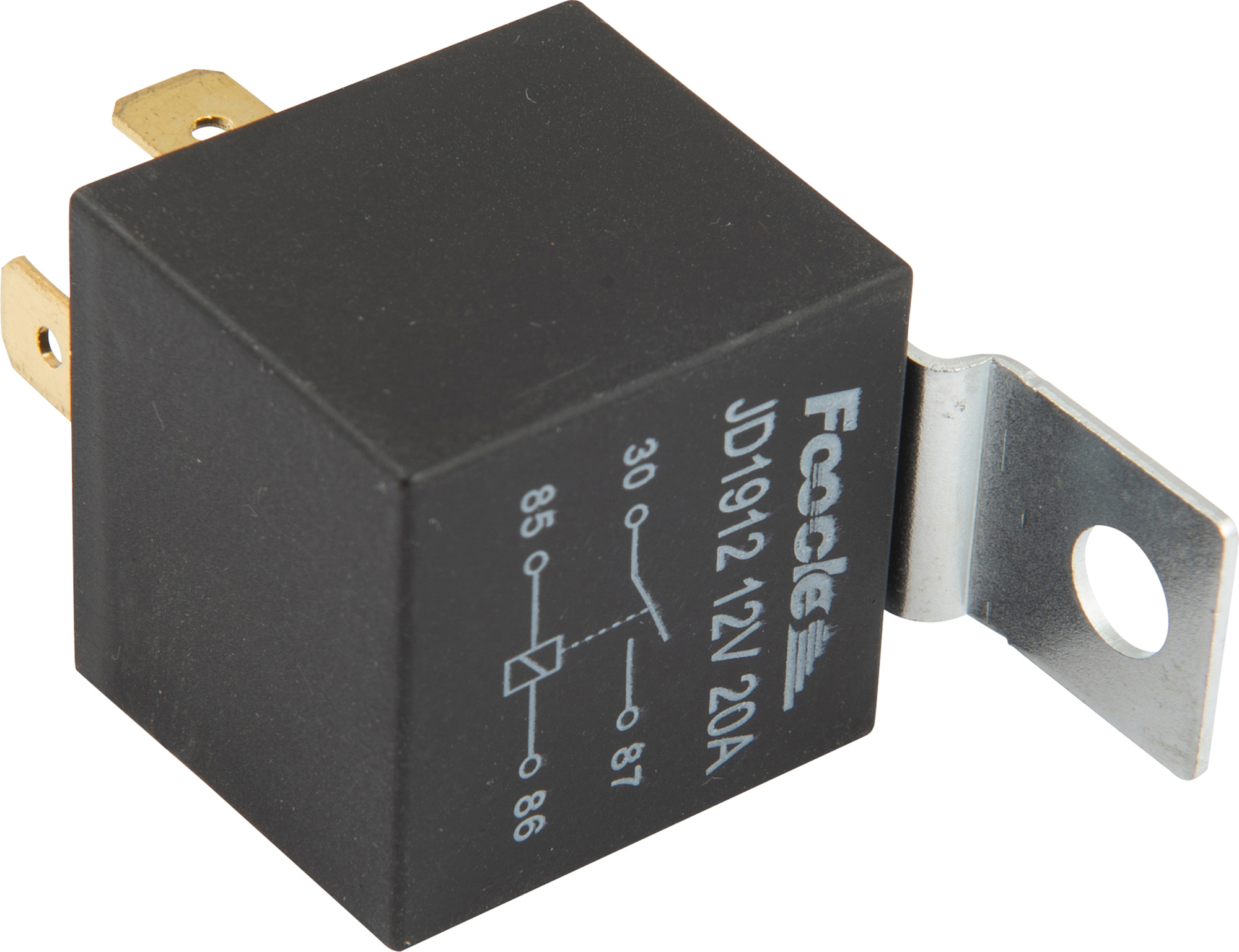
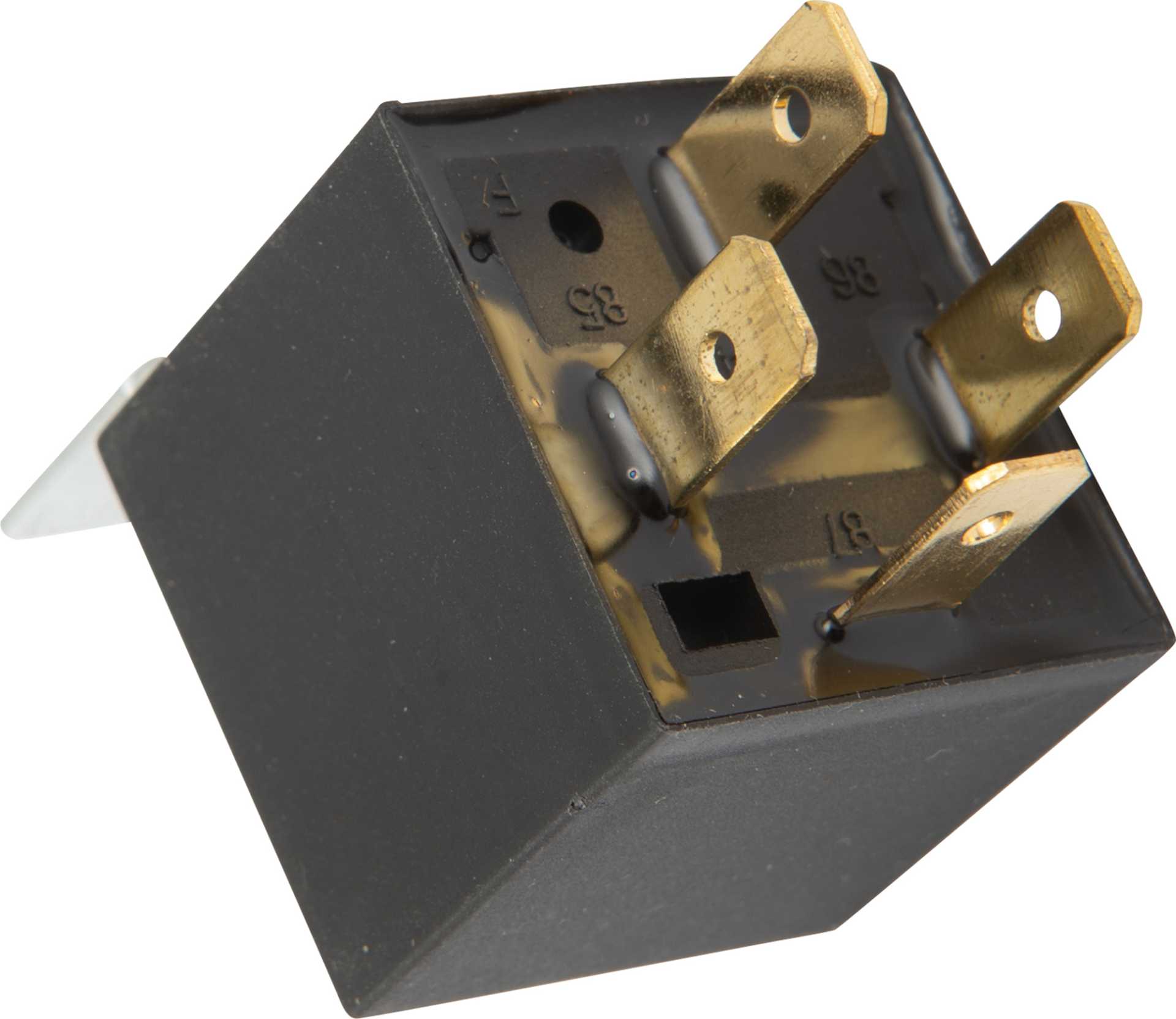
So I take a relay like that.
30 - wired to the ignition power from the Gauges fuse.
87 - Indicator light
86 - Main Contact
85 - Parking Brake (that little purple wire I was playing with)
Is that correct?
and if so where do i find the wire for the main contact?
Thanks.
|
|
|
