
 
     |
| Can't Get Speedo to Work after 3800 Swap (Page 1/2) |

|
Stricken
|
JAN 10, 08:17 PM
|
|
I've swapped the 3800SC/4t65 into my 88 Formula, and I cannot get the Speedometer to work. I have checked continuity all the way from the buffer circuit to the board of the Speedo. I have replaced all of the components in the buffer circuit. VSS Low has a good ground. I have tried using another speedo (I think it's from an 85?), But that one does the same thing - reads zero with key on and no change when driving. It does lift the needle off the peg, so the Speedo itself seems to be operational.
I had gotten the speedo to give a reading when I was randomly probing with the multimeter. The reading was way off, but it did go up with speed. I have not been able to repeat this, however.
The PCM does have a VSS signal. It was tuned by ZZP, but I heard the tune might need to be adjusted to output the right signal for the buffer circuit? Doesn't make sense to me, but I'm out of ideas at this point.
Does anyone have any ideas or how I can generate a signal to test the Speedo? I'm about to give up and make my own gauge cluster.
|
|
|
|
Dennis LaGrua
|
JAN 10, 10:24 PM
|
|
You will need a simple RC circuit to shape the signal into something that the Fieros speedometer will recognize.
The Fiero Vss produces a sine wave of 4000 pulses per mile. With the 3800 a signal of 24,000 PPM is generated by its Vss but that signal is first sent to the PCM then inputted back to the speedometer In other words you need to buffer the 3800 PCM's speedometer output so that the Fieros speedometer can read it. You need to build a simple Vss converter that goes between the PCM speedomter output and the Fiero speedometer. I did it on my swap and it works well but I'll need to look up the values of the parts. ------------------
" THE BLACK PARALYZER" -87GT 3800SC Series III engine, custom ZZP /Frozen Boost Intercooler setup, 3.4" Pulley, Northstar TB, LS1 MAF, 3" Spintech/Hedman Exhaust, P-log Manifold, Autolite 104's, MSD wires, Custom CAI, 4T65eHD w. custom axles, Champion Radiator, S10 Brake Booster, HP Tuners VCM Suite.
"THE COLUSSUS"
87GT - ALL OUT 3.4L Turbocharged engine, Garrett Hybrid Turbo, MSD ign., modified TH125H
" ON THE LOOSE WITHOUT THE JUICE "
|
|
|
|
Stricken
|
JAN 10, 10:56 PM
|
|
| quote | Originally posted by Dennis LaGrua:
You will need a simple RC circuit to shape the signal into something that the Fieros speedometer will recognize.
The Fiero Vss produces a sine wave of 4000 pulses per mile. With the 3800 a signal of 24,000 PPM is generated by its Vss but that signal is first sent to the PCM then inputted back to the speedometer In other words you need to buffer the 3800 PCM's speedometer output so that the Fieros speedometer can read it. You need to build a simple Vss converter that goes between the PCM speedomter output and the Fiero speedometer. I did it on my swap and it works well but I'll need to look up the values of the parts.
|
|
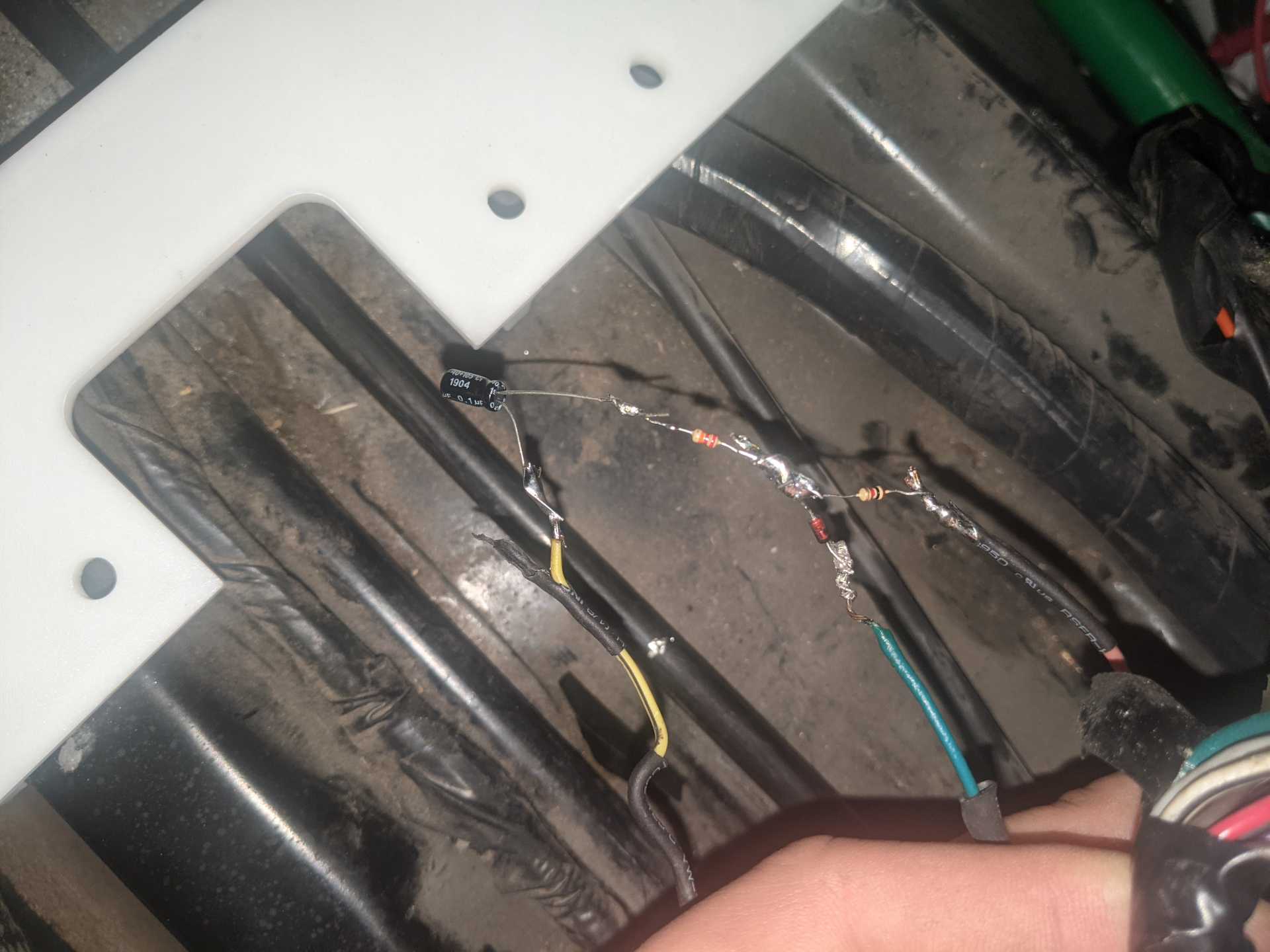
Yes, the harness came with the buffer circuit, but when the Speedo wasn't working, I replaced the resistors, diode, and capacitor to no avail. Here's what it looks like (please excuse the messiness as I've done a bunch of cutting/resoldering)
|
|
|
|
Dennis LaGrua
|
JAN 11, 08:17 AM
|
|
|
If you soldered directly to the diode ( or any other semiconductor device) without a clip on heat sink, you may have burned it out. You can test it with a VOM. The other suggestion is to re-check the wiring path from the PCM to the VSS adapter to the speedometer. Twelve volts must be supplied to the VSS adapter. Check for voltage. ------------------
" THE BLACK PARALYZER" -87GT 3800SC Series III engine, custom ZZP /Frozen Boost Intercooler setup, 3.4" Pulley, Northstar TB, LS1 MAF, 3" Spintech/Hedman Exhaust, P-log Manifold, Autolite 104's, MSD wires, Custom CAI, 4T65eHD w. custom axles, Champion Radiator, S10 Brake Booster, HP Tuners VCM Suite.
"THE COLUSSUS"
87GT - ALL OUT 3.4L Turbocharged engine, Garrett Hybrid Turbo, MSD ign., modified TH125H
" ON THE LOOSE WITHOUT THE JUICE "
|
|
|
|
Stricken
|
JAN 11, 08:32 PM
|
|
| quote | Originally posted by Dennis LaGrua:
If you soldered directly to the diode ( or any other semiconductor device) without a clip on heat sink, you may have burned it out. You can test it with a VOM. The other suggestion is to re-check the wiring path from the PCM to the VSS adapter to the speedometer. Twelve volts must be supplied to the VSS adapter. Check for voltage.
|
|
I just built the circuit again just twisting the wires together - no solder. Same thing.
I decided to disconnect the VSS lead coming from the PCM, and I'm seeing no AC voltage when driving around. I pulled the connector apart, and the pins and connectors look good. I have conductivity from the pin side of the connector all the way to the buffer circuit. I'm wondering if the PCM is just not putting out a signal? I had it tuned by ZZP, maybe they turned it off somehow?
|
|
|
|
Dennis LaGrua
|
JAN 12, 02:01 PM
|
|
| quote | Originally posted by Stricken:
I just built the circuit again just twisting the wires together - no solder. Same thing.
I decided to disconnect the VSS lead coming from the PCM, and I'm seeing no AC voltage when driving around. I pulled the connector apart, and the pins and connectors look good. I have conductivity from the pin side of the connector all the way to the buffer circuit. I'm wondering if the PCM is just not putting out a signal? I had it tuned by ZZP, maybe they turned it off somehow? |
|
Your circuit uses a diode and en electrolytic capacitor. Both must be installed in the correct polarity as per the circuit. I'll try to look up the circuit schematic that I used
------------------
" THE BLACK PARALYZER" -87GT 3800SC Series III engine, custom ZZP /Frozen Boost Intercooler setup, 3.4" Pulley, Northstar TB, LS1 MAF, 3" Spintech/Hedman Exhaust, P-log Manifold, Autolite 104's, MSD wires, Custom CAI, 4T65eHD w. custom axles, Champion Radiator, S10 Brake Booster, HP Tuners VCM Suite.
"THE COLUSSUS"
87GT - ALL OUT 3.4L Turbocharged engine, Garrett Hybrid Turbo, MSD ign., modified TH125H
" ON THE LOOSE WITHOUT THE JUICE "
|
|
|
|
Stricken
|
JAN 15, 12:36 PM
|
|
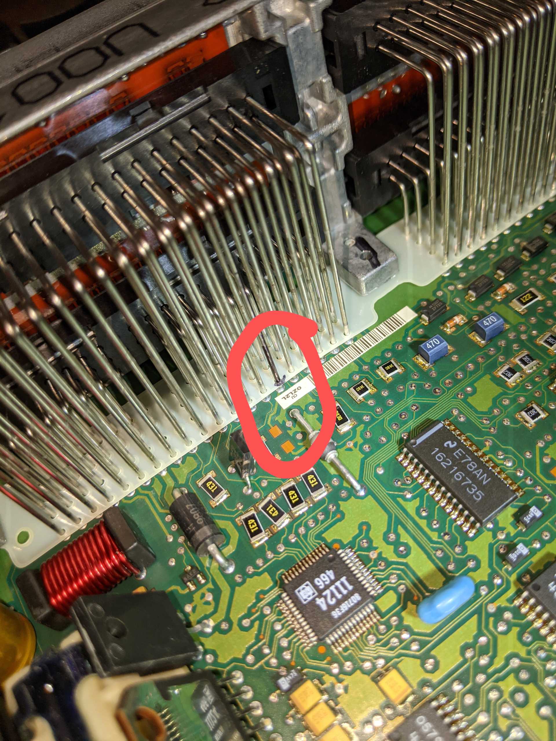
I got an oscilloscope multimeter on it, and confirmed that the PCM is not putting out the VSS signal. I decided to take it apart to see if there was a broken pin inside. It appears to be missing a resistor at the VSS Out trace. The was an exchange pcm from ZZP, so maybe the car that this came from was missing an option like cruise control so they left the circuit open?
|
|
|
|
Stricken
|
JAN 15, 05:55 PM
|
|
|
I went and bought a junkyard PCM, and the Speedo works with that, so the exchange PCM from ZZP was the issue. Interestingly, that resistor is missing on this PCM too. There is a trace on the back side which is where the signal must come from.
|
|
|
|
olejoedad
|
JAN 16, 07:58 AM
|
|
The first mistake was using a ZZP tuned PCM in a Fiero swap.
Was the 4K signal coming from C1 (blue) 55?
|
|
|
|
olejoedad
|
JAN 16, 09:41 AM
|
|
The first mistake was using a ZZP tuned PCM in a Fiero swap.
Was the 4K signal coming from C1 (blue) 55?
|
|
|
|