
 
     |
| My approach to wiring up Danyel's LED 3rd brake light panel (Page 1/1) |

|
Trinten
|
SEP 30, 08:45 PM
|
|
So a few year back when Danyel announced a sale on things he was selling... I bought one of everything. Seriously.
One of the things was his 3rd brake light LED. Now I fully admit I had not read up on his thread on this particular product, and at the time, no one was making a 90-degree turn "drop in" red LED bulb solution for that socket type. Even today there are a few. I bought a set from Amazon to do some compare and contrast with at some point.
Anyhow, when I looked at it and the instructions, I was a little disappointed. It required the (careful) de-soldering (or otherwise separation) of the standard bulb from a socket, then either soldering the new wires from his panel on, or using hot glue. If I recall, the instructions for mounting of the LED panel in the housing were also "use hot glue", which I was not thrilled with. But hey, my own fault for not doing research. And it was a chance for me to mess around on something inexpensive.
I got out my soldering iron and heated up the prongs where the bulb popped off with just a slight tilt. Excellent.
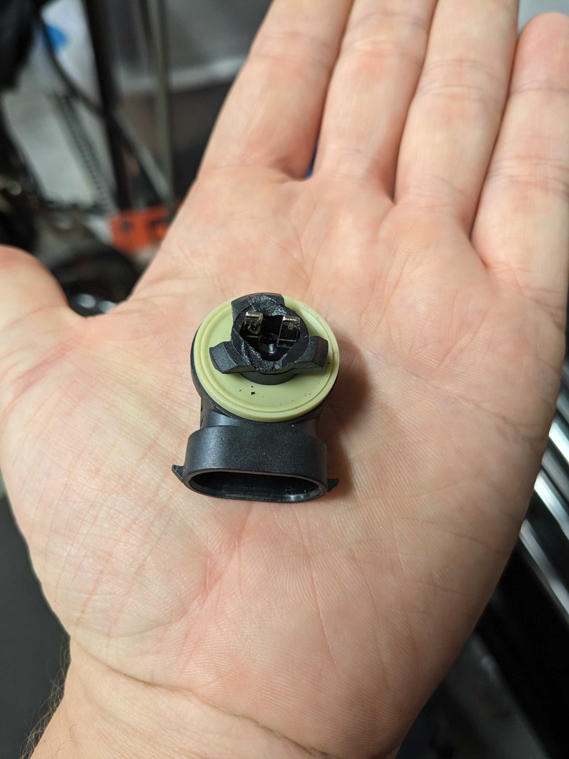
Next, I tried to solder on the new connectors. In the process of this failure, the heat started to melt the base a little, which is what made me pause. While I was considering that issue, I started to ask myself "How would this even go into the housing if I managed to solder this?!" the panel wouldn't fit through the bulb opening, and the base can't wiggle out from the inside then secure into place.
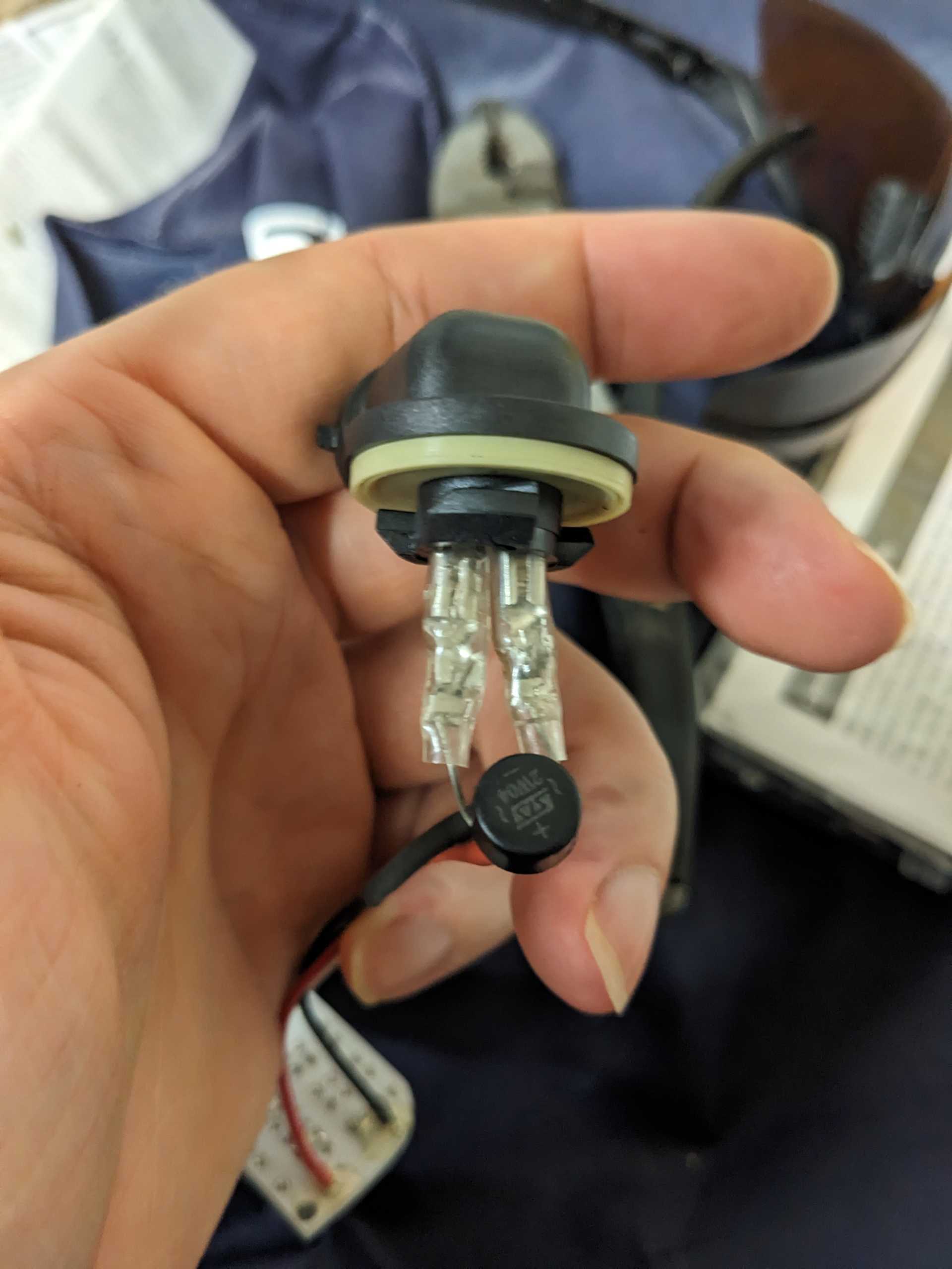
So I got out my micrometer, and measured the blades in the base. 2.88mm. Okay, so then I went and found a spade connector kit that included 2.88mm connectors:
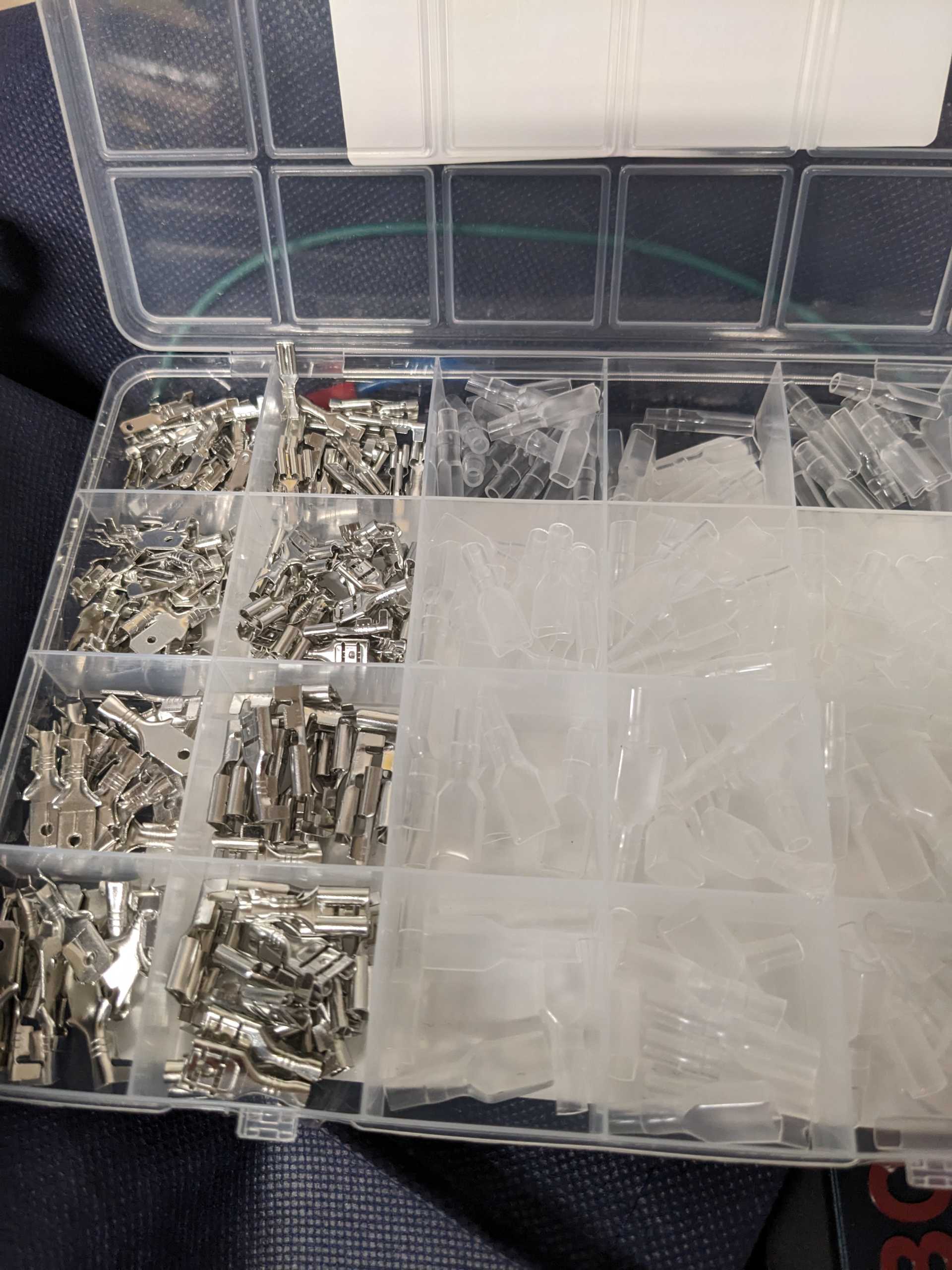
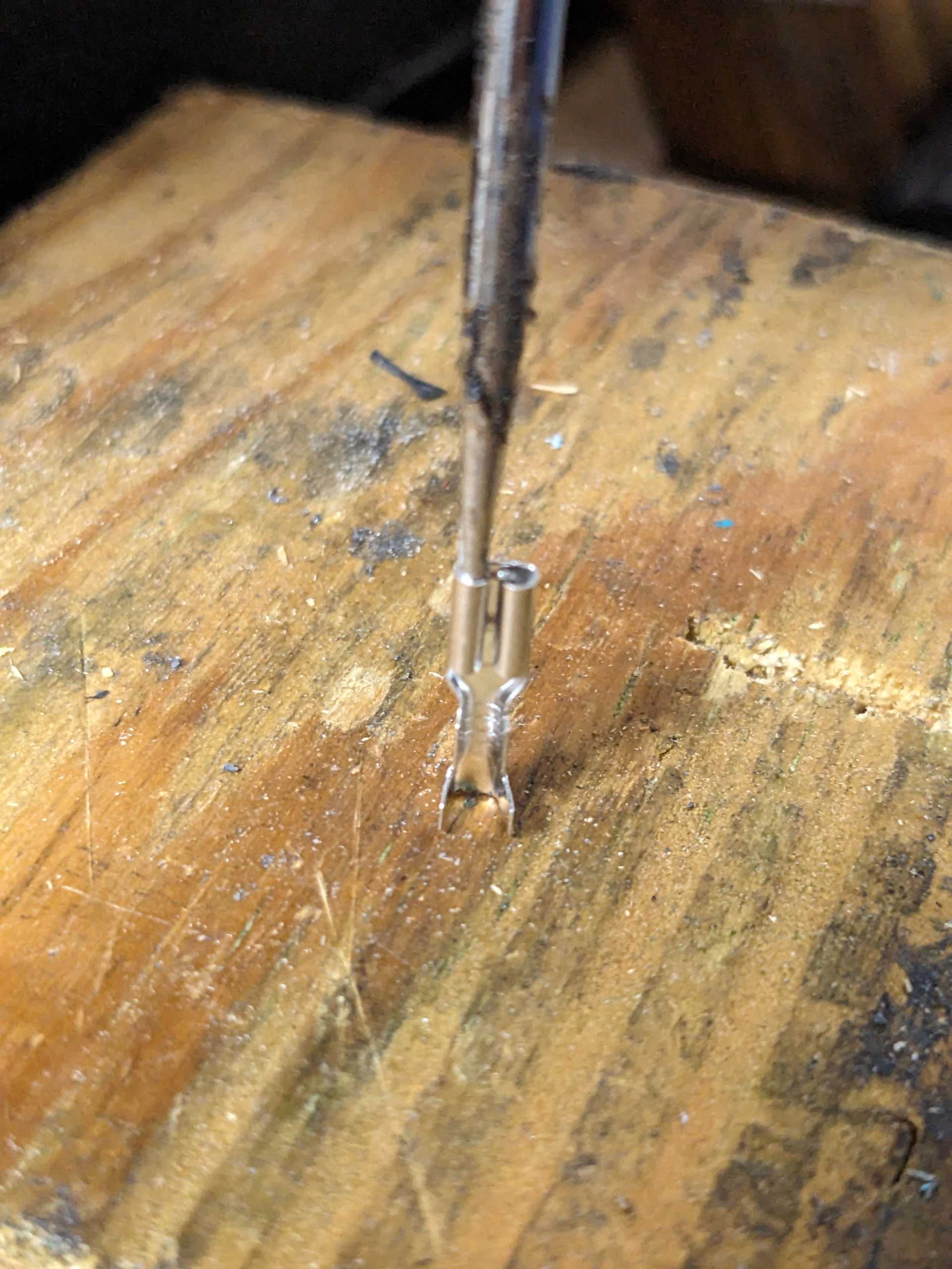
With these in hand, I did a test fit. The connector was designed for a thinner blade. No problem. I get out a pick, insert, set it on a block of wood, and lightly tapped the back of the handle with my palm.
Just taaaap it in.

After a few test fits to make sure it was open just enough for a snug fit, I slid the insulator over the wire on the panel, then fed the connector in. Sadly the wire lead wasn't long enough to clear the insulator from the connector completely, so I had to be gentle so the metal didn't cut through it. I probably should have put a tiny bit of shrink tube on the wire to give the connector more to grip, but didn't think about it at the time.
I also did one completely before I stopped and said "Hey... I should probably take some pictures of all this and put a post up!" So... that's why you can sorta see one done in this picture.
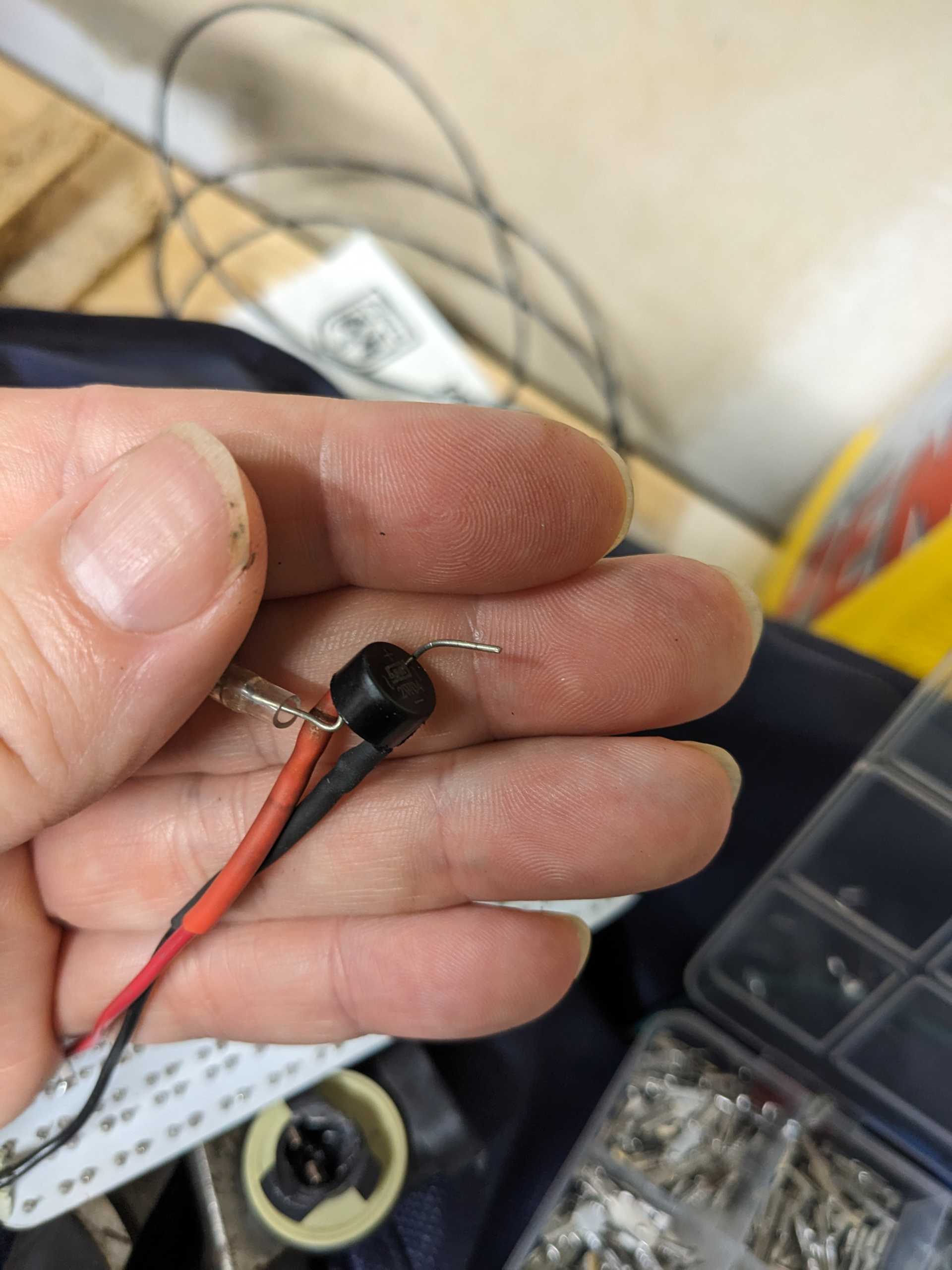
After getting them crimped, I gave them the pull test. Then fit them on the bulb, and did another pull test to disconnect them to make sure the connectors stayed on the wire. Success!
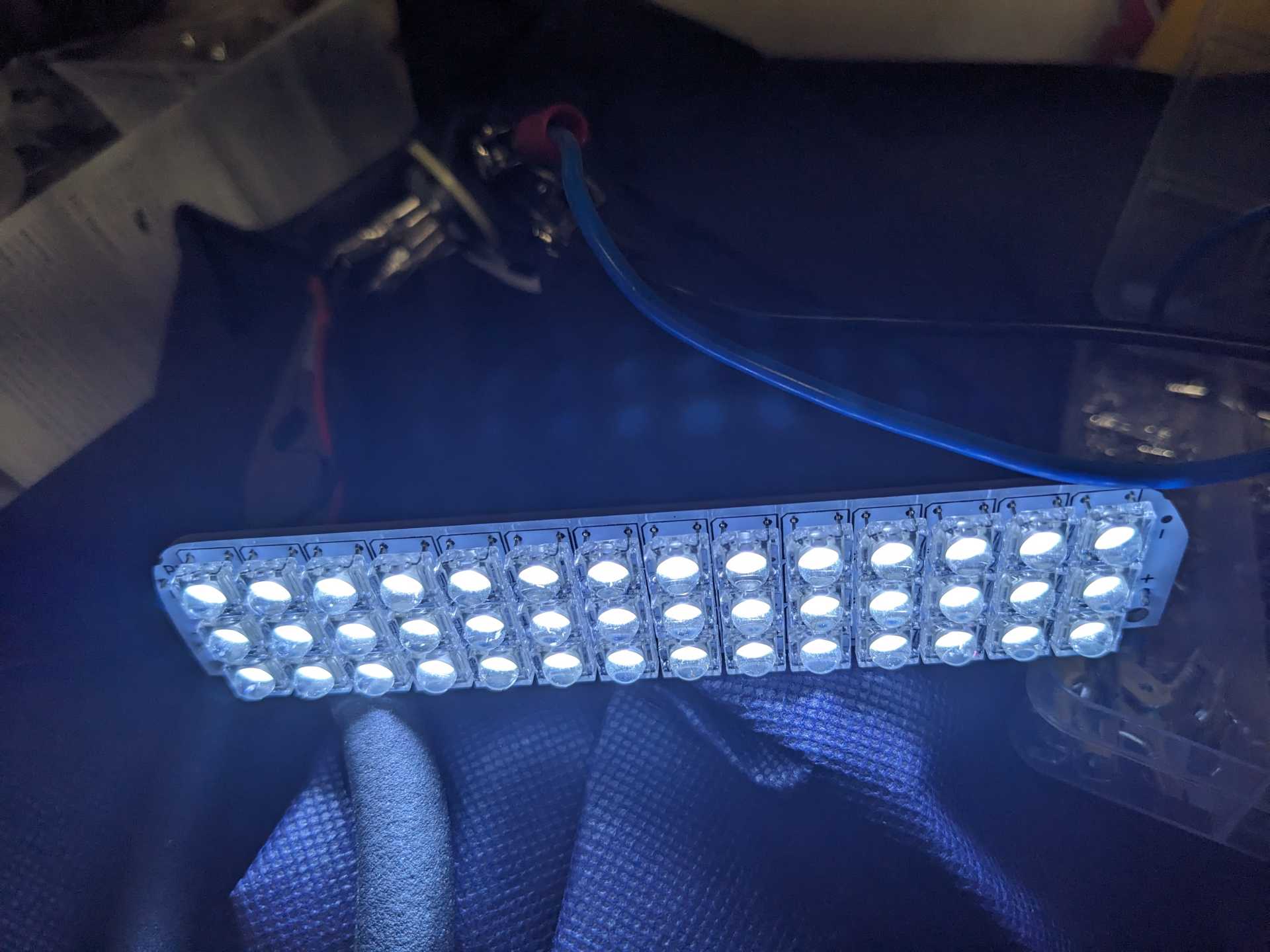
And finally connecting some power to test it out.
Now to finalize my improved mounting solution. I'll update the thread with that once I'm done and happy with it.
Then after I get a chance to do some side by side comparisons (standard bulb, panel LED, and Amazon LED), I can see if there's any worth in pursuing trying to make an improved LED panel kit, one that is ready to plug and play.[This message has been edited by Trinten (edited 09-30-2024).]
|
|
    
  |
|
