First the website is incorrect in their calculations. The CFM per square inch is the wrong value. Here is the correct CFM ratings. 52mm flows 300.5 cfm 65mm flows 375.7 cfm.
The formula is: Diameter in inches X Pi X 46 = CFM
Second, those will only fit "J" body intakes. The bolt pattern is too wide to use on a Fiero intake.
NOTE: The above is incorrect. See post below for correct formula's and calculations. The above formula is only for carb's.
------------------ Happiness isn't around the corner... Happiness IS the corner.
[This message has been edited by Oreif (edited 09-20-2002).]
IP: Logged
01:08 AM
1FST2M6 Member
Posts: 3905 From: Dallas, GA. Registered: Jan 2000
First I'm not using the stock Fiero 2.8 intake manfolds. I'm either going to use a modified multi-TB setup for the 3.4 aluminum intake or the stock 3.4 intake with larger TB like above.
Based on those calc's 207 * 7000 / 3456 = 420 cfm. So even with the 65mm TB the air flow is still not enough for the 7K redline I'm looking for.
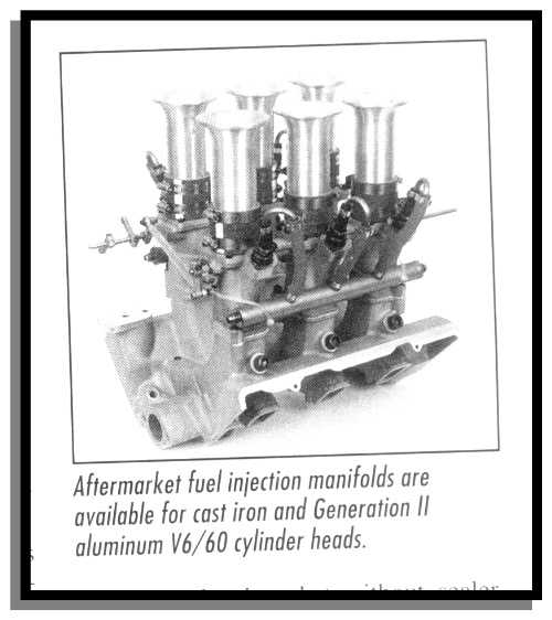
I guess it's the modified intake setup. I'm trying to find out who manufactures this setup. I don't care for the down draft pipes, I'm thinking more like cowl induction set up through the rear decklid scoop. But the thought has crossed my mind that with the scoop backwards will it affect the air flow through the scoop?
Thanks,
Earl R.
[This message has been edited by FieroGT87 (edited 09-19-2002).]
IP: Logged
09:33 AM
1FST2M6 Member
Posts: 3905 From: Dallas, GA. Registered: Jan 2000
What camshaft and valve train are you going to use? Most cams for 60* V-6's make peak power around 5000-5500 rpm and the 65mm TB is good up to about 6400rpm. Cut your redline down to 6500 and your just about there.
IP: Logged
09:52 AM
FieroGT87 Member
Posts: 3195 From: St. Louis, Mo, USA Registered: Jul 2001
IIRC, that pic is from the Chevrolet Power book. I've never seen that setup for sale anywhere, though. (To be fair, I haven't really looked very hard.)
Sure would be nice, though!
[EDIT] ...posts that cross in the "cloud".
------------------ Raydar
I'm not the pheasant plucker. I'm the pheasant plucker's son. But I'll pluck pheasants 'Til the pheasant plucker comes.
[This message has been edited by Raydar (edited 09-19-2002).]
IP: Logged
09:54 AM
Oreif Member
Posts: 16460 From: Schaumburg, IL Registered: Jan 2000
Originally posted by FieroGT87: I guess it's the modified intake setup. I'm trying to find out who manufactures this setup. I don't care for the down draft pipes, I'm thinking more like cowl induction set up through the rear decklid scoop. But the thought has crossed my mind that with the scoop backwards will it affect the air flow through the scoop?
You know if you don't mind the look of the Indy scoop, Showcars makes the SD4 version which is an indy scoop with a 12" X 12" X 4" high box to the right side. (it basically fits over the center of the V-6 engine.) A rough scaling of the pic shows you should be about 1" above a GT decklid and that will leave 3" of clearence. Just a thought.
IP: Logged
09:56 AM
FieroGT87 Member
Posts: 3195 From: St. Louis, Mo, USA Registered: Jul 2001
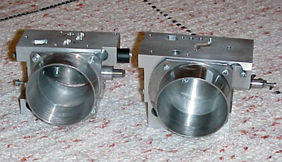
You might want to check out Darrell Morse's modified Fiero Throttle bodies. I believe that they are bored out 52mm units. Adding a much larger throttle body shouldn't help all that much. The Fiero plenum is rather restrictive for larger displacements V6's especially so on the 3.4L. You can port them a bit but they really need extrude honing to flow more.
Daryl was the person I thought of when I started putting the idea together for this 3.4 upgrade. I was trying to find the post to how far Daryl could bore out the TB, but I now know it's not enough. I need a TB of around 70mm if I use the stock 3.4 intake manafold to get the 420cfm I need.
I'm leaning very heavily to the manafold/TB setup made by Kinsler. It looks like you've got 6 smaller seperate butterflys, one for each cylinder with the fuel injection set up. I can only guess but I would bet that that setup could handle up to around 700cfm which is much more than I need. I'll see what else they have.
As far as the air intake problem, my GT has Mecham scoops on both sides. Maybe I can run some tubing down to both sides for the cold air intake there.
[This message has been edited by FieroGT87 (edited 09-19-2002).]
IP: Logged
11:58 PM
Sep 20th, 2002
Oreif Member
Posts: 16460 From: Schaumburg, IL Registered: Jan 2000
Darrel bores them out 5mm. So you get a 57mm TB. With the plenum bored out you get 330cfm. Even polishing or extrude honing the intake manifold and plenum, You still are drawing air thru a 57mm TB.
See corrected CFM formula below
[This message has been edited by Oreif (edited 09-20-2002).]
IP: Logged
12:55 AM
Unltd1 Member
Posts: 912 From: Morrison, CO 80465 Registered: Jun 2002
On that 6 separate TBs that you are talking about.. Seriously watch ebay I saw the TBs go for like $100 for all 6, then a few weeks later a manifold went for like $200. Also As far as a Billet TB, I have been talking with Franz of FDP performance and they are working on a 58mm TB... well I measured some clearances and stuff and am going to see if I can hog out the TB hole to 60 or 62mm. If so I think we should have a 60-62mm TB for those of us with the 3.4 Fiero at some point... (I'm just a consumer of these also not the builder) anyways I will post some more info at a later date... By the way here is what is posted about TBs support for Horsies....(care of 60degreev6.com)
quote
TB Calculations (by Chris Williams)
For every square inch of butterfly, you will flow 140 CFM.(OreiF says its wrong so this may be way off). To calculate the air flow for a 2" butterfly, you need to calculate the area first. Area = pi X radius squared. So, 1/2 of 2" is 1 inch, squared is still 1, times pi (3.14) = 3.14 square inches of butterfly area. This means that it will flow enough air for approximately 440 CFM, or 314 horsepower.
62mm=2.44" = 3.14149x(1.22)^2=4.67sq/in x 140=653
(the numbers in ()'s are adjusted to Oreif's calculation method [diameter * 3.14 * 46=cfm ] ...I don't know which is right...)
So by those numbers technically a 52 would do ok for the job, but then again look at the redone Oreif numbers... I must say that if Oreifs formula is right, then some serious TBs need to be used...
[This message has been edited by Unltd1 (edited 09-20-2002).]
IP: Logged
01:35 AM
Oreif Member
Posts: 16460 From: Schaumburg, IL Registered: Jan 2000
Originally posted by Unltd1: So by these numbers technically a 52 would do ok for the job. More later...
NO, The formula that is listed on the website is incorrect. See my post above for the correct formula.
Here is a question: A SQUARE inch butterfly flows 140 CFM per the website. So If I have a square throttle plate, 1" X 1" It should flow 140 cfm. Now if I have a round throttle plate 1" in diameter, Your telling me it equals 1.57 SQUARE inches of butterfly??? What's wrong with this picture?? Take a sheet of paper and cut out a 1" X 1" square. That is 1 square inch. Now take a sheet of paper and cut out a 1" circle. Place circle on square. How is the circle 1.5 square inches when it is smaller than the 1" square??
(The formula I noted above was taken out of a Holley intake design book)
[This message has been edited by Oreif (edited 09-20-2002).]
IP: Logged
02:03 AM
Unltd1 Member
Posts: 912 From: Morrison, CO 80465 Registered: Jun 2002
Originally posted by Oreif: You know, I was looking at his formula on the other website. I found his "area" error. Area is Pi X radius SQUARED. So a 2" butterfly would be: Radius 1" squared is .5
what 1" squared should still be 1"
IP: Logged
02:26 AM
Nashco Member
Posts: 4144 From: Portland, OR Registered: Dec 2000
The LT1 TBs are twin throttle plates. I dont know if this is accurate but from another discussion, twin 52mm will flow 750 CFM and the twin 58 mm will flow 1000. I know its somewhere close though based on the aftermarket LT1 TBs. This would mean chris' formula is wrong. I can't just take someones word for it this time though, so I will need to see how that formula works. Thanks for bringing it up though, I dont like having incorrect info on the site.
------------------ Ben www.60degreev6.com
IP: Logged
02:59 AM
Oreif Member
Posts: 16460 From: Schaumburg, IL Registered: Jan 2000
OK, Here it is. I searched the internet, and read thru the Holley book again. Carb's The formula I have (diameter in inches X Pi X 46 = CFM) Is NOT for open throttle bodies. It is a calculation for average street Carb's. Street carbs have a different flow characteristics than an open faced throttle body because of the choke plate and venturi's in the barrel. Pure race carb's are different. These can (by design) have VE's higher than 1.0 and are calculated the same way as multi-barreled Throttle bodies. (see below)
A street carb's flow is calculated using Air Density, Throttle bodies and race carbs are calculated by Air Mass. Kind of the same difference from using a MAP sensor and a MAF sensor for fuel injected engines.
Single bore throttle bodies The formula on the 60* V-6 website is not wrong, just incomplete. It is only part of the formula. You need to multiply it by the VE than divide it by 1.5hg's. Per the Holley book, a single barrel TB has a VE of 1. (this is assuming a round faced single barrel TB. An oval faced TB could have a higher VE by design and then would have higher CFM rating) So as an example we'll use the stock Fiero TB. 52mm is 2.05" throttle plate has 3.3sq/in which is 462, X VE (which is 1) is 462. Divided by 1.5 = 308 CFM.
Multi-Barrel Throttle bodies Now according to Holley a 2-bbl throttle body like the units used on LT1's need the VE calculated based on the opening at the face of the throttle body and the height of the airfoil in between the 2 butterfly plates. They generally have a VE of over 1.0. They have a airfoil that replaces the stock one on LT1 throttle bodies that increases the VE and gives you 36 more CFM than stock. The VE is based on the amount of air just in front of the butterfly plate. So you can technically increase CFM on a Throttle body without increasing the butterfly plate sizes.
Note: Throttle Body Injection units have an average VE of .95
Boost from a turbo or supercharger increases your VE even on a single barrel throttle body. I have not looked for that calculation, I'm still on my first cup of coffee. (should I switch to decaf?? )
See what happens when I get some sleep? (yes 1" squared is 1")
------------------ Happiness isn't around the corner... Happiness IS the corner.
[This message has been edited by Oreif (edited 09-20-2002).]
IP: Logged
10:30 AM
Rare87GT Member
Posts: 5086 From: Wichita, KS USA Registered: Oct 2001
I wish our 3.4's had some aftermarket for throttle bodies and intake manifolds to flow more air. I have Darrel Morse's porting tb and manifold but it still just doesn't do the job, although it helps there is still much more air to flow on our 3.4's. Im just really surprised that a company hasn't marketed something for the 3.4's as an upgrade or so forth. How many people on the forum have custom fabricated a 3.4 TB or Manifold? Any pics? HP Numbers? Just was curious.
My question is, Even if you mated a 70mm TB to the plenum (just for the sake of arguing here) aren't the intake runners still restrictive?? Or are they adaquate enough, just that they can't all feed through the 1 small TB?
------------------ 18 Year Old Fierophile. --1986 GT Daily Driver, NX 50 Shot, Borla exhaust, ported manifolds, and a few other goodies --1984 SE 4.9, IMSA spoiler, Duel exhuast, GT rear bumper, Konis, drop spindles, Rear adjustable perch, Poly total kit, Poly cradle bushings, Big front bar, Added rear bar, 11.25" brakes on all corners w/SS hoses, Fancy wheels wrapped w/soft rubber, and much much more.
IP: Logged
12:12 PM
Dan Robinson Member
Posts: 482 From: South Milwaukee, WI Registered: May 2001
So........which size would I use if I was building a intake manifold?
------------------ DiZZI
Matthew 11:28,29 28"Come to me, all you who are weary and burdened, and I will give you rest. 29Take my yoke upon you and learn from me, for I am gentle and humble in heart, and you will find rest for your souls." www.geocities.com/captain_cu_cu/danro.html
[This message has been edited by Dan Robinson (edited 09-20-2002).]
IP: Logged
01:18 PM
Unltd1 Member
Posts: 912 From: Morrison, CO 80465 Registered: Jun 2002
Originally posted by Oreif: See what happens when I get some sleep? (yes 1" squared is 1")
I figured you had to be tired at that point to... Nice find on that! Also what holley book is it? I know you know your shite so I was tending to trust your numbers, (and the fact that those other numbers were so high was making me sceptical) I was digging for the truth and the almight Oreif gave it to us! VE is Volumetric Efficiency in Percentage (converted to Decimal)right??
IP: Logged
01:38 PM
Oreif Member
Posts: 16460 From: Schaumburg, IL Registered: Jan 2000
Originally posted by Unltd1: Also what holley book is it? VE is Volumetric Efficiency in Percentage (converted to Decimal)right??
Volumetric Efficiency (VE) Is the ratio of actual mass of air taken into the engine, to the mass the engine displacement would theoretically consume if there were no losses. So yes it is a percentage. The reason you can get higher than 100% is because air pressure (in Hg's) and air temp affect the actual air mass and it's scaled to the theoretical mass.
The book is "Holley Carburators, Manifolds, & Fuel Injection" by HP Books. It is the updated 4th edition. "It covers history, selection, installing, tuning, repair, and modifying of fuel system components for street and racing use."
IP: Logged
02:16 PM
Oreif Member
Posts: 16460 From: Schaumburg, IL Registered: Jan 2000
Originally posted by Jncomutt: My question is, Even if you mated a 70mm TB to the plenum (just for the sake of arguing here) aren't the intake runners still restrictive?? Or are they adaquate enough, just that they can't all feed through the 1 small TB?
Well..... This is a whole different thing. Once the throttle portion is done then you need to calculate out the intake manifold. Size of ports, style of manifold, length of runners, etc. all need to be calculated out. Then You need to do the same for the heads. The book I have doesn't go into detail on calculating flow thru an intake manifold. It just covers the many different styles and their pro's and con's of each.
IP: Logged
02:44 PM
Doug Chase Member
Posts: 1487 From: Seattle area, Washington State, USA Registered: Sep 2001
Great thread. Thanks for the heads up in the other thread where you pointed it here.
One question, though.
quote
Originally posted by Oreif: Volumetric Efficiency (VE) Is the ratio of actual mass of air taken into the engine, to the mass the engine displacement would theoretically consume if there were no losses. So yes it is a percentage. The reason you can get higher than 100% is because air pressure (in Hg's) and air temp affect the actual air mass and it's scaled to the theoretical mass.
There will always be losses in the induction system so it seems to me that VE can never be above 100% just based on air temp and pressure. Isn't the theoretical mass based on the ambient air temp and pressure? Or is theoretical mass based on say 1000 feet altitude at 70 degrees so if you're driving below sea level at 50 degrees you could have a VE > 1?
As far as I knew there were only two ways to get intake VE over 100%. One is forced induction (Dennis, in your above post you forgot to make your speech about how a turbocharger is the only practical way to get more air into our motors). The other is to have a tuned intake manifold that basically works like a header but on the upstream side of the motor.
Originally posted by Doug Chase: Great thread. Thanks for the heads up in the other thread where you pointed it here.
One question, though.
There will always be losses in the induction system so it seems to me that VE can never be above 100% just based on air temp and pressure. Isn't the theoretical mass based on the ambient air temp and pressure? Or is theoretical mass based on say 1000 feet altitude at 70 degrees so if you're driving below sea level at 50 degrees you could have a VE > 1?
As far as I knew there were only two ways to get intake VE over 100%. One is forced induction (Dennis, in your above post you forgot to make your speech about how a turbocharger is the only practical way to get more air into our motors). The other is to have a tuned intake manifold that basically works like a header but on the upstream side of the motor.
Please fill me in on what I'm missing.
True the entire induction system has losses. The VE is for the TB itself. This is just the flow of the TB not the entire induction system. So with a wider area in front of the throttle plate of dense air, You could flow more air than theoretically what the area of the throttle plate should flow.
IP: Logged
08:23 PM
FieroGT87 Member
Posts: 3195 From: St. Louis, Mo, USA Registered: Jul 2001
Update I talked with Kinsler today and they said they only make those set-ups for the 90 degree engines both 6 and 8's.
I'm still searching. Scott at Kinsler said a company called Wessel Racing specializes in 60 degree V6 engines with a similar set-up. The phone number he gave me was 217-337-6369. I tried it and they said the area code had changed to 260. I tried that number and it's been disconnected.
I need everyone's help here to find this set-up.
Thanks,
Earl R.
IP: Logged
11:16 PM
FieroGT87 Member
Posts: 3195 From: St. Louis, Mo, USA Registered: Jul 2001
You asked about the Cam shaft. The one I'm thinking about has a .394 intake lift with a duration of 276* from lash point and .410 exhaust lift 293* from lash point. This is the high output cam from GM. This cam upper end is 6500 rpm's, but I'm still looking.
Full roller rockers with a Heavy valve spring that applies 140 lbs of seat pressure.
I'm using the Gen III aluminum heads and lower intake.
IP: Logged
11:30 PM
Oreif Member
Posts: 16460 From: Schaumburg, IL Registered: Jan 2000
You asked about the Cam shaft. The one I'm thinking about has a .394 intake lift with a duration of 276* from lash point and .410 exhaust lift 293* from lash point. This is the high output cam from GM. This cam upper end is 6500 rpm's, but I'm still looking.
Full roller rockers with a Heavy valve spring that applies 140 lbs of seat pressure.
I'm using the Gen III aluminum heads and lower intake.
That cam is too small. That is the cam that is in the stock Fiero 2.8L. I would think with the higher rpm range and larger fuel system, you would want something in your RPM range.
How about the Crower 3050? HI-DRAULIC HAULER / PERFORMANCE LEVEL 4 - Strong mid-range and top end torque and horsepower. RPM Power Range: 2200 to 6200 / Redline: 6500 plus.
That intake manifold in my opinion looks to goofy. I don't like that look but if it help in power that's great. I just think we need something that looks OEM and that is all about performance. I really don't understand why someone on the forum hasn't made one as many people on here would purchase or at least try something new to see some dyno numbers. The 2.8L intake is like making the engine have nothing have 3500rpms. The 3.4L seems like one of the popular engine swaps like the Caddy 4.9L but it seems that its just a swap in and nothing to add to help performance. What has been the highest horsepower dyno or 1/4 mile time on the track with a 3.4L with or without nitrous? Kind of curious. See ya. I know Dennis LaGaura's car would probably run somewhere in the 13's but his is turbo charged. What are most guys running on a 3.4L and what mods were done. I would like to know.
I'm very confused with all the equations. Would someone like to walk me through a dual 52mm throttle body for a 4.9 V8 at 5,250 RPM? Thanks in advance.
IP: Logged
06:56 PM
Sep 26th, 2002
FieroGT87 Member
Posts: 3195 From: St. Louis, Mo, USA Registered: Jul 2001
Originally posted by Wipe0ut: I'm very confused with all the equations. Would someone like to walk me through a dual 52mm throttle body for a 4.9 V8 at 5,250 RPM? Thanks in advance.
4.9L = 302.33 Cubic inches times 5250 (rpm) Divided by 3456 is 459cfm required. Twin 52mm TB (assuming oval face with equal height air foil) is 655 cfm. You would be able to draw in more air than the engine could theoretically draw in. What would happen is, if you floored the engine from a standstill, it would bog down until the RPMs could get high enough to overcome the low vacuum. Your throttle response would be poor. You would be better off with a 65mm single barrel TB.