So this 88 front headlight harness I got, it came with a working cooling fan relay!... Haven't had one of those in years..It works, but I would like to hook up a green LED that comes on in the dash, when the cooling fan does...Just so I can keep an eye on this old relay....
Would anyone know how I could do this...What wires I the harness, or instrument panel will send a low voltage signal when the fan comes on...?
------------------
IP: Logged
07:47 AM
PFF
System Bot
Pyrthian Member
Posts: 29569 From: Detroit, MI Registered: Jul 2002
i did this on my bike. the LED is easier to mount somewhere since its small, will use less power. use resisters in line to get the voltage down to about 1.5 volts. i want to think that i have seen higer voltage LEDs somewhere though
IP: Logged
11:28 AM
Graudefas Member
Posts: 352 From: Sauk City, WI, USA Registered: Jul 2002
Pardon the light bulb 'smiley'; they don't (have an LED smiley...)
You can use an LED; you'll want about a 620 Ohm 1/2 watt resistor (radio shack) in series with it. In other words, ground one end of the LED, connect other to the resistor, other end of the resistor to the fan. A terminal block helps make sure connections last awhile.
LEDs are current-driven devices; red ones have about a 1.2 volt drop needed across them to light; yellow and green are about 2 volts. Calculate current draw by taking battery voltage (charging) minus the drop, then dividing by the desired current (say, 20 milliAmps) and you'll have a good idea of the resistance you'll need.
Example: (13.6v - 1.2v)/0.02 = 620 Ohms
Note that different manufacturers of LEDs have different conventions as to which LED lead is negative (ground) so you'll have to try each way. Some LEDs have a longer lead which is usually +; others have a flat that usually indicates -. But not all are the same.
If the LED is too bright, you can increase the value 'til you're happy with the outcome.
IP: Logged
02:38 PM
Graudefas Member
Posts: 352 From: Sauk City, WI, USA Registered: Jul 2002
Oh, yeah... forgot to add that I would personally use a scotchlock connector up by the fan connector up in the front, AFTER the relay. That way, you'd know if the relay was working or not. If you tapped into the signal for the relay, you'd only know that the switch was closing... not that the fan motor was actually energized.
IP: Logged
02:42 PM
Seanpaul Member
Posts: 1320 From: Santa Rosa, North CA. Registered: Mar 2003
So by using a resistor before the led, I can connect the unit to the fan power!..? I thought that the fan leads were high amps..and would fry any else...
Graudefas...I'm not sure If I understand, let me see....
13.6v - 1.2v)/0.02 = 620Ohms
13.6 volts is the voltage of the car running. 1.2 volts is the voltage needed to power the LED???
= 12.4 volts remaining.
Now we calculate the resistor needed by determining the current used??
The LED takes 20ma with a 1.2 volt input??
So the total equation is (Operating voltage - LED voltage) / LED current = Resistor Ohm;s required?
------------------
IP: Logged
07:14 PM
Seanpaul Member
Posts: 1320 From: Santa Rosa, North CA. Registered: Mar 2003
Hey about the resistor...Do I want a small one like a 1/4 or 1/2 watt...or should I get a big 10 watt...? It just seems the current form the fan would require a large resistor to keep the temp down...
1. You can get nice mounted LED indicators... Some even come with the correct resistor for the LED. (I think all the ones at Radio Shack need you to add a resistor except the 120V indicators.)
You can get these a bunch of places and they aren't teribly expensive. Gives a nice finished look to things all on one step.
2. Assuming you want actual relay status... You just need to run a wire from the relay output (Black & Red) to the LED and wire another to ground. You can use almost anything for this that can handle 12V.
3. The resistor has nothing to do with the fan current. It is only between the LED and relay and is strickly dealing with LED current, which is tiny. Any small reisistor will do. 1/4 watt is usually fine. (The LED is a branch off the fan wire, not in series with the fan...)
The resistor doesn't have to be exact. In fact a resistor that is higher ohms than required might be good depending on where you mount the LED. This would dim the LED so it won't blind you at night if it turned on. As noted above, feel free to play with it.
You don't want the resistor to low ohms or you will toast the LED.
In most cases... Unless I need full LED output I just throw something around 1000 ohms on it. That will usually work for nearly any type/color LED.
------------------ No good ever came from dark and spooky. Norville "Shaggy" RogersThe Ogre's Fiero Cave (It's also at the top of every forum page...)
IP: Logged
08:29 PM
Aug 15th, 2003
Seanpaul Member
Posts: 1320 From: Santa Rosa, North CA. Registered: Mar 2003
So basically the LED is ran on a parallel circuit, so it will only draw a small amount of voltage from the out put of the relay... But the amount of voltage the LED will draw will not affect the fan in any way as the fan is relayed to it's own circuit..?
Ahh...the thing I for got is, this is DC and DC is direct current that will supply DC to any thing hooked in to the circuit, then the only thing we have to consider about the LED is the current it will take form the DC system as a hole..??
Does any have a diagram of the cooling system circuit...
IP: Logged
02:32 AM
Graudefas Member
Posts: 352 From: Sauk City, WI, USA Registered: Jul 2002
the LED's current addition is negligee... I mean negligable... and the fact that the fan motor proper draws heavy amps doesn't matter to the LED. Yes, the LED is in parallel with the fan motor.
In case you're interested in MORE equations, (I didn't think so! but here goes...) the power dissipated in the resistor is current squared time resistance. In my earlier example, it's (0.02 x 0.02) x 620, or 1/4 watt. Resistors should be sized twice what they dissipate to allow for ambient heating etc, so use a 1/2 watt resistor.
IP: Logged
09:09 AM
ka4nkf Member
Posts: 3702 From: New Port Richey, FL USA Registered: May 99
I went to Radio Shack and they have small LED'S with resistor already built in them. Get a 12 Volt and all you have to do is connect one lead to a hot wire and the other lead to the green and white stripe under the dash at the wire bulkhead above the gas pedal. I think it is about the fourth wire up from the left side of the wire bulk head. It will only come on when Fan comes on. I have mine mounted on the panel where the auto trunk swith is It makes it nice because you cane pick up your hot wire from the auto trunk switch. Remember the higher the milliamp the brighter the bulb. I think mine was 1.5 milliamp. sure looks good. Don
IP: Logged
09:11 PM
PFF
System Bot
ka4nkf Member
Posts: 3702 From: New Port Richey, FL USA Registered: May 99
I think he wants to see when the relay is actually closed. In that case the wire I said above would be correct. He will need to run a wire from the relay all the way back to the dash.
Connecting between 12V and the green/white wire would tell only if something is trying to turn on the fan. It wouldn't tell if the relay actually turned on.
Even with an indicator on the relay line, it doesn't guarantee the fan is on... a bad fan motor or wire to it could still keep it from spinning up.
IP: Logged
09:44 PM
Aug 16th, 2003
Seanpaul Member
Posts: 1320 From: Santa Rosa, North CA. Registered: Mar 2003
Yes Ogre you're correct, I want to make sure the relay is operational at all times, by actually seeing the fan indicator LED come on.. I used to wire the relay out of the circuit, but driving with the fan on at all times, is loud, and unnecessary...Now that I lucked in to a good relay, I would like to keep an eye on it...
Ka...One thing I don't understand...The wire you mentioned under the dash, it's a ground? And you hook up the LED to a hot and the neg to the fan ground..? Well because it's a ground, isn't it always grounded? Or does the ECM act as a grounding box, and it connects the ground as the signal is sent, and thus the circuit is operative..?
That would make sense, the ECM being a box that just grounds to complete circuits.... A box that would hold actual current would tend to burn out....??
IP: Logged
03:11 AM
buddycraigg Member
Posts: 13620 From: kansas city, mo Registered: Jul 2002
run a long wire up front to the fan like ogre says and your lite will come on when power is sent to the fan motor. and you just have to hope that the motor is working.
------------------ Buddy *there are two "G"s in my name* Ling = 84SE 350 N2O Poly MrMike seats Sequentials "unnamed"=85GT stock (mostly) KCFOG
IP: Logged
05:10 AM
rogergarrison Member
Posts: 49601 From: A Western Caribbean Island/ Columbus, Ohio Registered: Apr 99
Im like Buddy. I think all you need is a 12v led or lamp. Wire it with 1 lead on the wires right at the fan itself and 1 to power. When the fan IS on, it will light up. Everyone seems to want to make it too complicated.
I've used the led from Radio Shack with the built-in resistor to illuminate the window switches. They work very nicely, and just spliced one side of them to the light wire for the ash trays, and the other side to grnd. They're about $2 each, & have been installed for a couple of years now. I would expect they would last a comparative amt of time when hooked up to your fan harness.
roger, it all depends on what you call complicated. I was going to do this once, & use 2 leds. A green one, hooked to =12v and the other side tied into the free/wht wire that goes to the fan temp sw. It would illuminate when the switch closed at 235*. A red led would be connected to the 12v wire going to the fan itself, and grounded. It would illuminate when the relay closed. (earlier years). if the green one came on, I would know the switch was working ok. If the red one didn't come on, I would know that the switch was working, but the relay failed to close. A little more work, but it would simplify troubleshooting later.
IP: Logged
01:49 PM
The_Raven Member
Posts: 203 From: Brantford Ontario Registered: Aug 2003
maryjane: That's actually a cool idea, but a little overkill. LOL
This is such a simple circuit....
You have one light (meaning LED or bulb, or??) one side will be connected to a good ground source (if it's an LED the shorter leg), then the other side is connected to the fan output from the relay (if using an LED use a 1K ohm resistor in series with this wire. works very well, I usually attach it to the LED directly)then as the fan comes on, so does the light.
You could even take this one step farther and use an unused "idiot light" hole in the gauge cluster for a stealthy install. One step farther than that, would be to have "cooling fan" on that space where the light is.
IP: Logged
04:22 PM
Aug 18th, 2003
ka4nkf Member
Posts: 3702 From: New Port Richey, FL USA Registered: May 99
Seanpaul The green and white wire that I refered to in the bulkhead above the gas pedal is the groun wire to the fan switch on the engine It is not grounded until the fan switch closes which completes the circuit for the fan to come on.I like this setup and it is easy. you can hook it to the fan relay ground and it will do the same thing. The relay is hot all the time with Ign. switch on, then when the car gets hot and the fan switch on the engine makes up the ground then the fan comes on. if it does not come on then you got a bad fan switch on the engine or a bad relay. If you run a toggle switch to the green and white wire and the other lead to ground then you can turn the fan on any time you wish just by flipping the switch. lots of Fiero has this type set up. hope this clears it up for you. Don
IP: Logged
01:18 AM
Seanpaul Member
Posts: 1320 From: Santa Rosa, North CA. Registered: Mar 2003
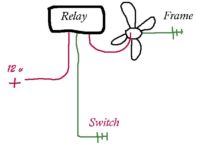
Thanks for the detail Don...umm, but im still in the dark, does anyone have a detailed diagram of the circuit..? I'm aware now of where I need to put the indicator, but now my quest is to figure out this system..
This is what I'm thinking...
- Cooling fan: One side is grounded to frame, power is provided by relay when activated. - Relay: One side is grounded via: the cooling switch, power is provided by ignition.
- Cooling switch: the switch grounds, and provides the ground needed to activated the relay, thus provides the power leg to the fan?
I've included a very sloppy diagram of how I think this system works...
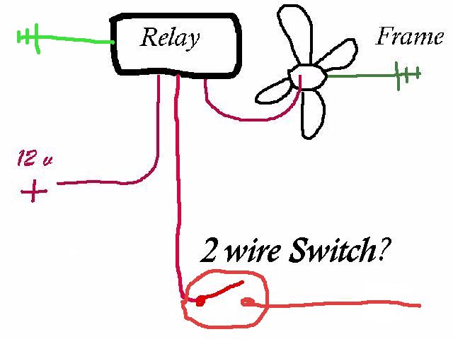
OR.....would the system work like this...??
- Cooling fan: One side is grounded to frame, power is provided by relay when activated. - Relay: One side is always grounded, power is provided by ignition, AND COOLANT SWITCH PROVIDES SECONDARY VOLTAGE TO ENGAGE RELAY?
- Cooling switch: the switch activates, sends secondary voltage to relay?
IP: Logged
04:26 AM
Seanpaul Member
Posts: 1320 From: Santa Rosa, North CA. Registered: Mar 2003
no..no...no Number one has to be correct....The relay gets 30amps from fuse box, and when switch grounds, this creates the magnetic field to tos the switch for the fan to activate....If number 2 were the way, then that would mean that the power supply for the fan would have to run through the switch, and that wouldn't be good...
...am I on track now...??
IP: Logged
04:39 AM
PFF
System Bot
Seanpaul Member
Posts: 1320 From: Santa Rosa, North CA. Registered: Mar 2003
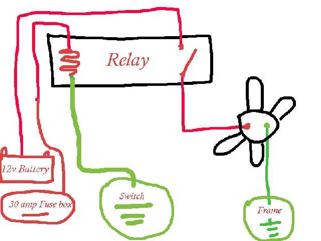
Your diagram is pretty much right. There is a fusible link between the battery and the relay. There is an additional relay activation circuit from the A/C system. According to a 1986 schematic I'm looking at, it is done by the High Pressure Cutout Switch, and a contact in the A/C climate control panel. Wire colors as follows:
batt --> relay: red relay --> fan: black/red fan --> ground: black fuse --> relay: brown/white relay to various activations: dark green/white
Your best bet is to tap into the wire going from the relay to the fan, run that wire through a small (<1 amp) fuse first, then run it into the passenger compartment to an LED, then a 1k resistor, then to ground. Use the Fuse, Luke! I still have scars on my hands from where I grabbed a red-hot wire that I'd run to my cooling fan, it shorted at the switch I'd installed and started burning, I yanked out of the car with my bare hands. Ouch! If I'd fused it at the relay, the fuse would've popped and saved me the agony. The fan fuse didn't pop because the wire was only drawing 20-30 amps, enough to start it burning but not enough to blow the fuse.


.JPG)