Pennock's Fiero Forum
  Technical Discussion & Questions - Archive
  240sx Dash installation (Page 2)

T H I S   I S   A N   A R C H I V E D   T O P I C
  

Email This Page to Someone! | Printable Version

This topic is 2 pages long:  1   2 
Previous Page | Next Page
240sx Dash installation by stuartlowery
Started on: 12-31-2003 01:12 AM
Replies: 52
Last post by: stuartlowery on 03-10-2004 10:46 AM
stuartlowery
Member
Posts: 1019
From:
Registered: Jul 2003


Feedback score: N/A
Leave feedback


Total ratings: 71
User Banned

Report this Post01-09-2004 01:15 AM Click Here to See the Profile for stuartloweryClick Here to visit stuartlowery's HomePageSend a Private Message to stuartloweryDirect Link to This Post
Page #2

I've tried my circuit and it has failed me. I don't know my since I don't have an ociliscope. but it has failed. So since that COST me $40 I'm going to scrap the idea of building my own and will be going with the Dakota Digital Module unless a sure win circuit shows up that's been tested.

IP: Logged
RCR
Member
Posts: 4416
From: Shelby Twp Mi
Registered: Sep 2002


Feedback score:    (7)
Leave feedback


Total ratings: 102
Rate this member

Report this Post01-09-2004 07:48 AM Click Here to See the Profile for RCRSend a Private Message to RCRDirect Link to This Post
Stuart, I'm curious as to the circuit you used. Can you post or send me a schematic? Also, note exactly what you're trying to do.

Bob

IP: Logged
stuartlowery
Member
Posts: 1019
From:
Registered: Jul 2003


Feedback score: N/A
Leave feedback


Total ratings: 71
User Banned

Report this Post01-09-2004 09:17 AM Click Here to See the Profile for stuartloweryClick Here to visit stuartlowery's HomePageSend a Private Message to stuartloweryDirect Link to This Post
http://users.otenet.gr/~athsam/frequency_doubler_with_4011.htm

I used this circuit along with a simple 9 volt regulator. Also I had to edit my PCB Layout since I found a mistake in it. I also didn't have much luck with making the PCB so I opted to use a project board. This circuit was used to Double the Frequency.

IP: Logged
RCR
Member
Posts: 4416
From: Shelby Twp Mi
Registered: Sep 2002


Feedback score:    (7)
Leave feedback


Total ratings: 102
Rate this member

Report this Post01-09-2004 11:54 AM Click Here to See the Profile for RCRSend a Private Message to RCRDirect Link to This Post
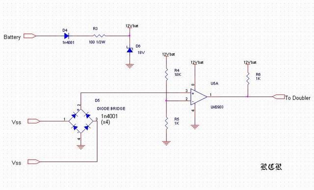
Does it work now that you found the mistake on the board? If not, try it without the 9V regulator. The 4011 is a CMOS part and can handle the 12V battery signal. If it works, protect the circuit with an 18V zener.

- I was thinking about your circuit. It probably won't work because you have a sine wave input. To make it work, you would need a full wave rectifier on the input to keep your sine wave pulses positive. Then you would have to gaurentee that the amplitude of the pulse was higher than the hi/lo thresholds of the 4011.

-- I threw something together quick. D4 gives you reverse bat protection. D6 will limit the voltage to the circuit to 18V. The rectifier will full wave rectify the input. The comparator will give you a high output when the input goes above about 1 volt. You can play with the resistors R4 & R5 to change this threshold.

[This message has been edited by RCR (edited 01-09-2004).]

IP: Logged
stuartlowery
Member
Posts: 1019
From:
Registered: Jul 2003


Feedback score: N/A
Leave feedback


Total ratings: 71
User Banned

Report this Post01-09-2004 01:37 PM Click Here to See the Profile for stuartloweryClick Here to visit stuartlowery's HomePageSend a Private Message to stuartloweryDirect Link to This Post
No no change

I think the reason is due to the circuit only using half of the signal. It's looking for a high low signal such that of a reed style sensor. So If I had found a circuit that would have two inputs and two outputs it may have worked. But it only looks for the HIGH LOW instead with only one input.I hope this makes sense.

IP: Logged
stuartlowery
Member
Posts: 1019
From:
Registered: Jul 2003


Feedback score: N/A
Leave feedback


Total ratings: 71
User Banned

Report this Post01-09-2004 01:56 PM Click Here to See the Profile for stuartloweryClick Here to visit stuartlowery's HomePageSend a Private Message to stuartloweryDirect Link to This Post

stuartlowery

1019 posts
Member since Jul 2003
You edited your post before I could finish mine so here's the rest. I have a feeling that the speedometer may not work with that type of pulse. But it's definately worth a shot.
IP: Logged
RCR
Member
Posts: 4416
From: Shelby Twp Mi
Registered: Sep 2002


Feedback score:    (7)
Leave feedback


Total ratings: 102
Rate this member

Report this Post01-09-2004 03:11 PM Click Here to See the Profile for RCRSend a Private Message to RCRDirect Link to This Post
The biggest problem I see is that the voltage drop across the rectifier may wash out small input signals. You could try schotkey diodes to reduce the voltage drop. I'm curious to see if this works for you.
IP: Logged
stuartlowery
Member
Posts: 1019
From:
Registered: Jul 2003


Feedback score: N/A
Leave feedback


Total ratings: 71
User Banned

Report this Post01-09-2004 10:56 PM Click Here to See the Profile for stuartloweryClick Here to visit stuartlowery's HomePageSend a Private Message to stuartloweryDirect Link to This Post
HOLY CRAP! Over 1,000 Views to this post. Must be some people wanting to do this conversion REALLY bad. Well As you can see by this post so far getting everything lined out isn't easy. But all in all this will be one of the BEST and probibly least expensive interior swaps that can be done. Probibly the most expensive part will be the converter to correct the speedometer. But I'll go ahead and help you go crazy with me.... I have some TRICKS up my sleeve for this install. It's going to be WILD when it's COMPLETELY DONE. I will say this though it will take a while to complete though, but everyone will be kept in the light on the entire thaught process, except for my CUSTOM tricks.
IP: Logged
stuartlowery
Member
Posts: 1019
From:
Registered: Jul 2003


Feedback score: N/A
Leave feedback


Total ratings: 71
User Banned

Report this Post01-10-2004 03:09 PM Click Here to See the Profile for stuartloweryClick Here to visit stuartlowery's HomePageSend a Private Message to stuartloweryDirect Link to This Post
Here's a link to the schematic I just made combining yours and mine together in one unit.
http://webpages.charter.net/stuartl/fiero/doubler2.jpg
IP: Logged
stuartlowery
Member
Posts: 1019
From:
Registered: Jul 2003


Feedback score: N/A
Leave feedback


Total ratings: 71
User Banned

Report this Post01-13-2004 01:16 AM Click Here to See the Profile for stuartloweryClick Here to visit stuartlowery's HomePageSend a Private Message to stuartloweryDirect Link to This Post
Ok now I have purchased recieved and tested the Dakota Digital SGI-5 Speedometer converter unit and it works great. I now have a properly working Speedometer. So at this time I'm putting the frequency double on the back burner until I can get the parts gathered up to build and test it. But believe me I will make one that WORKS! Especially since the Dakota Digital unit when converting for this set up cannot be calibrated to correct anything so the EXTRA's are worthless to me.

So anyway I'm in the process of figuring out the rest of the cluster. #1 Idiot lights are idiot proof since they are SO simple I have put them to last on my list.
So here's what I've got

FUEL LEVEL
Fiero is a 90 Ohm FULL and 0 Ohm Empty system.
24SX is a 0 Ohm FULL and 90 Ohm Empty System.
On this I believe I will go the mechanical fix route of flipping over the sender for the guage. Or there may be another way that I have over looked such as an electrical change to the guage it's self that also may be easy. I will figure this out with some testing.

TEMPERATURE
Fiero 1365 Ohms @ 100*F 38*C and 55 Ohms @ 260*F 127*C
240SX 70-90 Ohms @ 140*F 60*C and 21 - 24 Ohms @ 212*F 100*C
Now this one may be TUFF. But I'm thinking either a converter of some sort or a parallel circuit to change the resistances. Unless a 240SX sender can be converted to fit the other engines. Only down fall is the Fiero sender also has a switch in it that the 240sx doesn't.

TACHOMETER
After reading a little on the Fiero Tach it says at 60hz the Tach should read 1800 RPM On the Fiero cluster

After reading the 240SX FSM it says and I quote, "Check Voltage at terminals 12 and 22 at idle and 2000 RPM. Higher rpm = Higher voltage Lower rpm = Lower voltage Voltage should change with RPM." Well no kidding. So what now? So I risk my 24SX tach. Fed up to 12Volts DC into it on teh first test. Nothing happened, Then tried the Tone generator on the computer, still nothing. Unhooked the computer from the signal wire and it jumped. So I used the wall transformer putting out 2 Volts. Jumped to 1700 3.7 Volts 1800 RPM Now 5 Volts 1800 RPM WOOHOO
60hz=1800 RPM good deal!

So now two guages left and then the idiot lights. Oh have I mentioned how easy this is to figure out? No? Didn't think so.

HINT: If you try to do this install, INVEST in Migrane Headache Medications.

IP: Logged
stuartlowery
Member
Posts: 1019
From:
Registered: Jul 2003


Feedback score: N/A
Leave feedback


Total ratings: 71
User Banned

Report this Post02-14-2004 03:36 AM Click Here to See the Profile for stuartloweryClick Here to visit stuartlowery's HomePageSend a Private Message to stuartloweryDirect Link to This Post
For anyone following this I'm still working on it just have been a little on the busy side with the wifes car and job relations. Sorry for the delay.
IP: Logged
PFF
System Bot
RCR
Member
Posts: 4416
From: Shelby Twp Mi
Registered: Sep 2002


Feedback score:    (7)
Leave feedback


Total ratings: 102
Rate this member

Report this Post02-14-2004 08:19 AM Click Here to See the Profile for RCRSend a Private Message to RCRDirect Link to This Post
I know what you mean, Stuart.

Bob

IP: Logged
stuartlowery
Member
Posts: 1019
From:
Registered: Jul 2003


Feedback score: N/A
Leave feedback


Total ratings: 71
User Banned

Report this Post03-10-2004 10:46 AM Click Here to See the Profile for stuartloweryClick Here to visit stuartlowery's HomePageSend a Private Message to stuartloweryDirect Link to This Post
How long could this possibly take...... Well at my speed FOREVER! Mainly due to Job relations, house hunting, living in an apartment and Mainly the room I do my work in is full of Everything else we own. So this weekend along with other things I'm planning on boxing up more of the stuff in there and getting busy on it again. Oh I'll also have a Caddy Harness to convert really soon as well so that'll pull me away for about a week, maybe more. But I'll for sure get back on it soon. Especially if this house hunting goes well. (1 house being kept in mind)
IP: Logged
Previous Page | Next Page

This topic is 2 pages long:  1   2 


All times are ET (US)

T H I S   I S   A N   A R C H I V E D   T O P I C
  

Contact Us | Back To Main Page

Advertizing on PFF | Fiero Parts Vendors
PFF Merchandise | Fiero Gallery
Real-Time Chat | Fiero Related Auctions on eBay


Copyright (c) 1999, C. Pennock