Pennock's Fiero Forum
  Technical Discussion & Questions - Archive
  93-99 Northstar disassembled inspection

T H I S   I S   A N   A R C H I V E D   T O P I C
  

Email This Page to Someone! | Printable Version


93-99 Northstar disassembled inspection by AJxtcman
Started on: 04-23-2007 07:16 AM
Replies: 13
Last post by: AJxtcman on 04-28-2007 10:03 AM
AJxtcman
Member
Posts: 1098
From: Rock Hill SC
Registered: Nov 2006


Feedback score: N/A
Leave feedback

Rate this member

Report this Post04-23-2007 07:16 AM Click Here to See the Profile for AJxtcmanSend a Private Message to AJxtcmanDirect Link to This Post
Engine Cleaning and Inspection
I have a lot on my plate right now and it is easier to answer question, but I should post this. It may take some time to finnish it.
This should have been on the begining of this
Topic: 93-99 Northstar Engine assembling
https://www.fiero.nl/forum/Forum2/HTML/080614.html
.
Engine Cleaning and Inspection

------------------
Cadillac Tech
ASE MASTER TECH since 1988

86 Northstar Fiero
85 RX7 former SCCA car
56 TR3 small mouth 6.0L
Formerly Washougal WA Resident
A.J. Whiteley

IP: Logged
PFF
System Bot
AJxtcman
Member
Posts: 1098
From: Rock Hill SC
Registered: Nov 2006


Feedback score: N/A
Leave feedback

Rate this member

Report this Post04-23-2007 07:17 AM Click Here to See the Profile for AJxtcmanSend a Private Message to AJxtcmanDirect Link to This Post
Engine Block Cleaning and Inspection
Cleaning Procedure
Clean all gasket surfaces, the oil passages, the coolant passages and the engine block with solvent.
Clean all threaded holes with solvent. Be sure to remove any old thread sealant material.
Prior to the application of RTV sealant GM P/N 12378521 (Canadian P/N 88901148) or equivalent to the engine block seal groove clean the groove and mating surfaces of the upper engine block and the mating surface of the lower crankcase with cleaner solvent GM P/N 12378392 or 12346139 (Canadian P/N 88901247).
Visual Inspection Procedure
Inspect all threaded holes for damage or excessive debris.
Inspect the cylinder block for cracks in the cylinder walls, the coolant jackets and the crankshaft bearing webs.
If cracks are found, the cylinder block must be replaced.
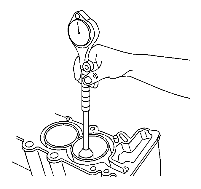
Cylinder Bore Diameter Measurement Procedure


Measure the cylinder bore diameter at 41 mm (1.61 in) below the cylinder block deck surface.
Compare your results with the engine mechanical specifications. If the cylinder diameter exceeds the specifications, the cylinder block must be replaced. There are no oversized pistons available for service.
Deck Face Flatness Measurement Procedure
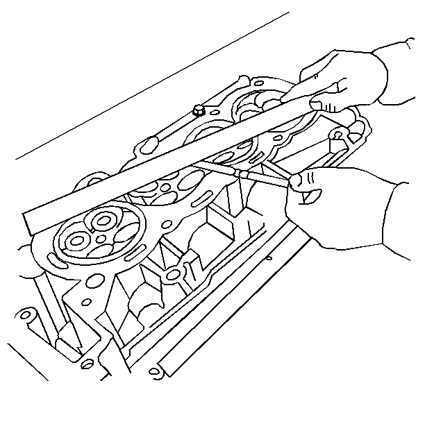
Place a straight edge across the deck face of the cylinder block at an angle starting at the front of the block and sloping downward to the rear of the block.
Measure the gap between the straight edge and cylinder block by sliding the feeler gauges under the straight edge at the front, center and rear of the block. Insert the greatest thickness gauge that will fit.
Find the difference between the largest and smallest measurement.
Change the position of the straight edge so that the angle travels up from the front of the block to the rear.
Measure the gap between the straight edge and the deck face again at the front, center and rear. Insert the greatest thickness gauge that will fit.
Find the difference between the largest and smallest measurement.
Position the straight edge so it travels through the center of the cylinder bores.
Measure the gap between the straight edge and the deck face a final time at the front, center and rear. Insert the greatest thickness gauge that will fit.
Find the difference between the largest and smallest measurement.
Compare your measurement to the engine mechanical specifications.
Important: If the flatness measurement exceeds the specifications, replace the cylinder block. Machining of the deck face surface is NOT allowed.

Cylinder Bore Taper Measurement Procedure
Measure the cylinder bore along the thrust surfaces (perpendicular to the crankshaft centerline) at 5 mm (0.20 in) below the deck surface and record your measurement.
Measure the cylinder bore along the thrust surfaces (perpendicular to the crankshaft centerline) at 102 mm (4.00 in) below the deck surface and record your measurement.
Calculate the difference between the two measurements. The result will be the cylinder taper.
Compare your results with the engine mechanical specifications. If the cylinders exceed these specifications, replace the cylinder block.
Cylinder Bore Out-of-Round Measurement Procedure
Measure both the thrust and non-thrust cylinder diameter 5 mm (0.20 in) below the deck surface. Record your measurements.
Calculate the difference between the two measurements. The result will indicate out-of-round at the upper end of the cylinder.
Measure both the thrust and non-thrust cylinder diameter 102 mm (4.00 in) below the deck surface. Record your measurements.
Calculate the difference between the two measurements. The result will indicate out-of-round at the lower end of the cylinder.
Compare your results with the engine mechanical specifications. If the cylinders exceed these specifications, replace the cylinder block.
IP: Logged
AJxtcman
Member
Posts: 1098
From: Rock Hill SC
Registered: Nov 2006


Feedback score: N/A
Leave feedback

Rate this member

Report this Post04-23-2007 07:32 AM Click Here to See the Profile for AJxtcmanSend a Private Message to AJxtcmanDirect Link to This Post

AJxtcman

1098 posts
Member since Nov 2006
Crankshaft and Bearing Cleaning and Inspection
Cleaning Procedure
Clean the following components in solvent:
• Crankshaft bearings

• Connecting rod bearings

• Crankshaft journals

• Crankpin journals

• Crankshaft oil passages

• Crankshaft threaded holes

Caution: Wear safety glasses in order to avoid eye damage.

Dry the following components with compressed air:
• Crankshaft bearings

• Connecting rod bearings

• Crankshaft journals

• Crankpin journals

• Crankshaft oil passages

• Crankshaft threaded holes

Visual Inspection


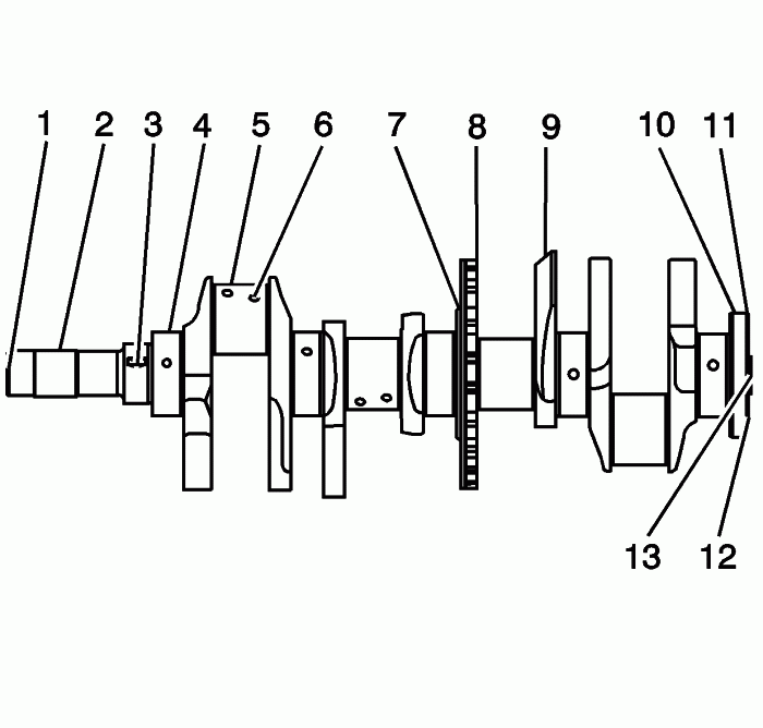
Perform the following visual inspections:
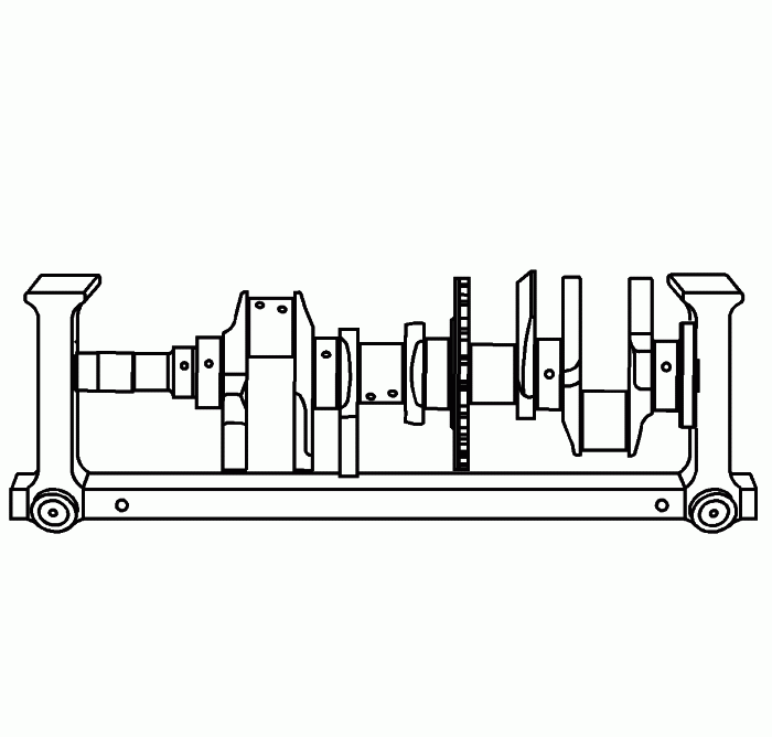
• Inspect the crankshaft balancer bolt hole (1) for thread damage

• Inspect the crankshaft balancer mounting area (2) for damage

• Inspect the crankshaft sprocket keyway (3) for damage

• Inspect the crankshaft main journals (4) for damage

• Inspect the crankshaft connecting rod journals (5) for damage

• Inspect the crankshaft oil passages (6) for obstructions

• Inspect the crankshaft main bearing thrust wall surfaces (7) for damage

• Inspect the crankshaft reluctor ring teeth (8) for damage

• Inspect the crankshaft counterweights (9) for damage

• Inspect the crankshaft rear main oil seal surface (10) for damage

• Inspect the crankshaft engine flywheel mounting surface (11) for damage

• Inspect the crankshaft engine flywheel bolt holes (12) for thread damage

• Inspect the crankshaft pilot hole (13) for damage

Repair or replace the crankshaft as necessary.
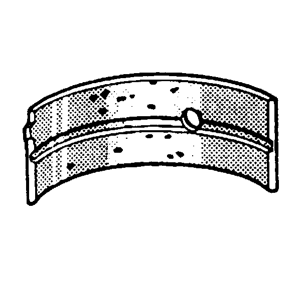
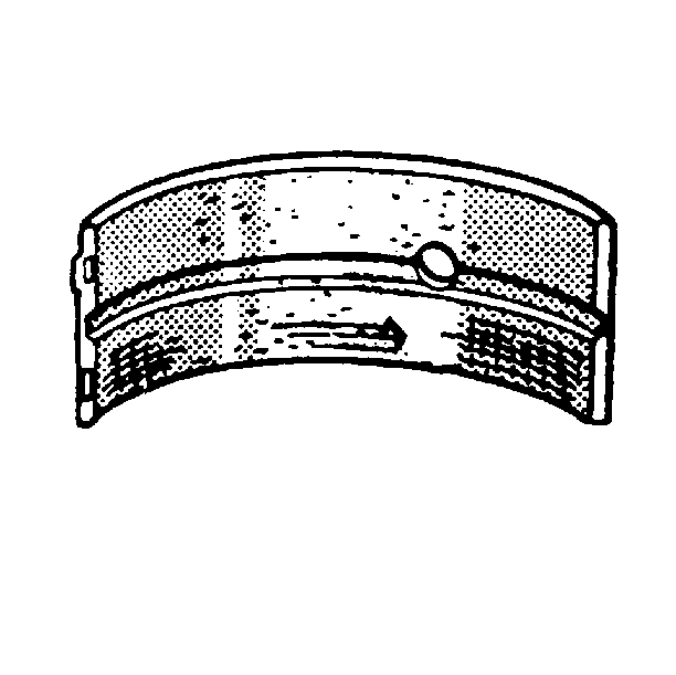
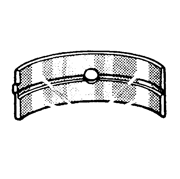
Crankshaft Bearing Inspection
Important: All connecting rod and main journal bearings that have been used in a running engine must be replaced. Never re-use the crankshaft or connecting rod bearings.

The following bearing wear conditions should be used to diagnose engine operating conditions or root cause of a condition.


Inspect for fatigue indicated by craters or pockets. Flattened sections on the bearing halves also indicate fatigue.


Inspect for excessive scoring or discoloration on both front and back of the bearing halves.
Inspect the main bearings for dirt imbedded into the bearing material.


Inspect for improper seating indicated by bright, polished sections.
Crankshaft Measurement
Tools Required
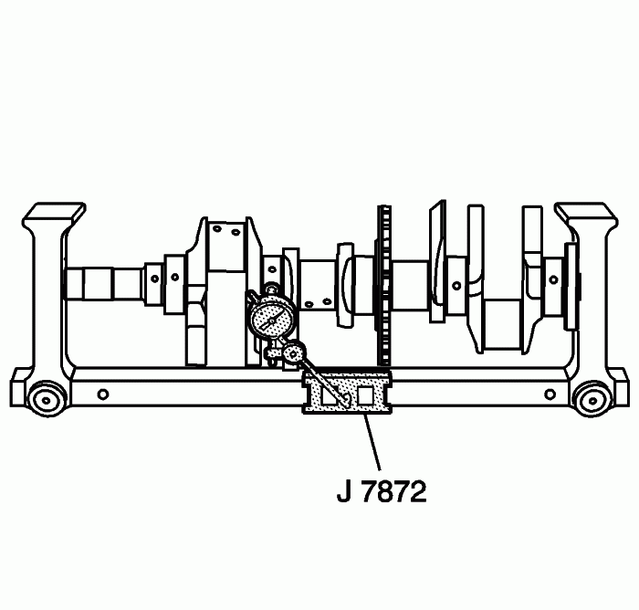
J 7872 Magnetic Base Dial Indicator


Using a suitable fixture, support the crankshaft.


Install the J 7872 .
Measure the crankshaft runout using J 7872 . Refer to Engine Mechanical Specifications .


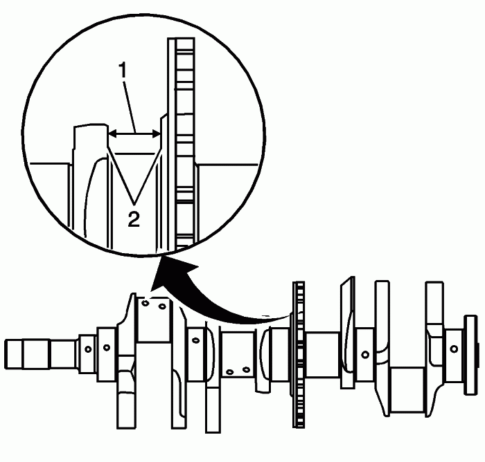
Measure the crankshaft thrust wall width (1) for wear using an inside micrometer. Refer to Engine Mechanical Specifications .
Measure the crankshaft thrust wall surface (2) for runout using J 7872 . Refer to Engine Mechanical Specifications .
If the crankshaft thrust walls are damaged or worn beyond specifications, replace the crankshaft. No machining of the crankshaft thrust wall is allowed.


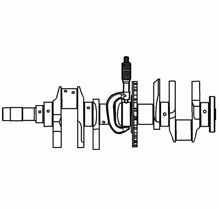
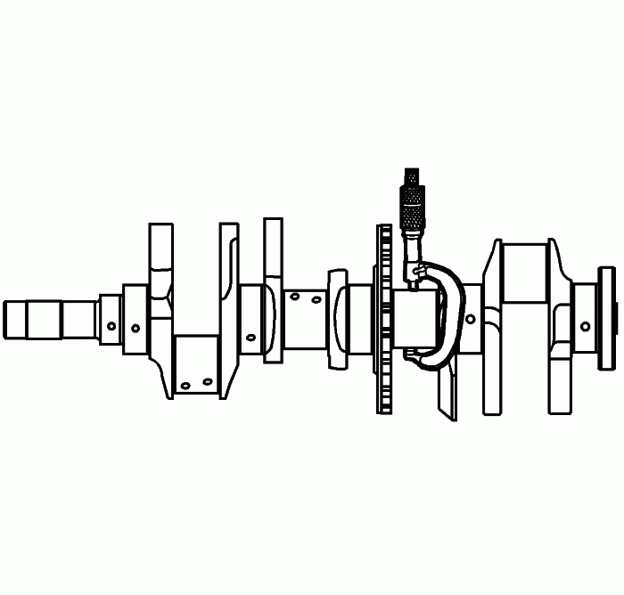
Check the crankshaft main journals for undersize using an outside micrometer.


Check the crankpins for undersize using an outside micrometer.
Compare your measurements with those listed in the Engine Mechanical Specifications . If the crankshaft journals are worn beyond the specified limits, the crankshaft must be replaced. Crankshaft machining is not allowed and there are no undersized bearings available for service.


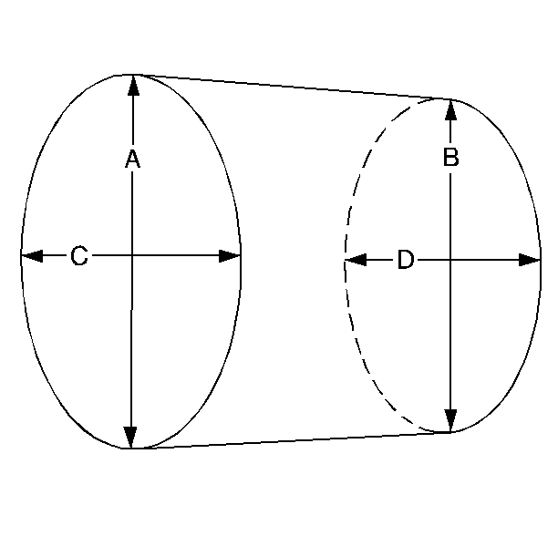
Measure the main bearing and crankpin journals for out-of-round using the following procedure:
10.1. Using an outside micrometer, measure the journal at the extreme front and rear locations on the journal. Call these points A and B.

10.2. Measure the journal in two new locations exactly 90 degrees from the first points. Call these points C and D.

10.3. Subtract A from C and B from D. The differences will indicate journal out-of-round.

10.4. The out-of-round should not exceed 0.005 mm (0.00020 in.) maximum.

10.5. If the specifications are exceeded, replace the crankshaft.

Measure the main bearing and crankpin journals for taper using the following procedure:
11.1. Using an outside micrometer, measure the journal at the extreme front (A) and rear (B) of the journal parallel to the crankshaft centerline.

11.2. Subtract the smallest from the largest measurement. The result will be the journal taper.

11.3. If the main bearing journal taper exceeds 0.008 mm (0.00032 in), replace the crankshaft.

11.4. If the crankpin journal taper exceeds 0.008 mm (0.00032 in), replace the crankshaft.

IP: Logged
AJxtcman
Member
Posts: 1098
From: Rock Hill SC
Registered: Nov 2006


Feedback score: N/A
Leave feedback

Rate this member

Report this Post04-23-2007 07:38 AM Click Here to See the Profile for AJxtcmanSend a Private Message to AJxtcmanDirect Link to This Post

AJxtcman

1098 posts
Member since Nov 2006
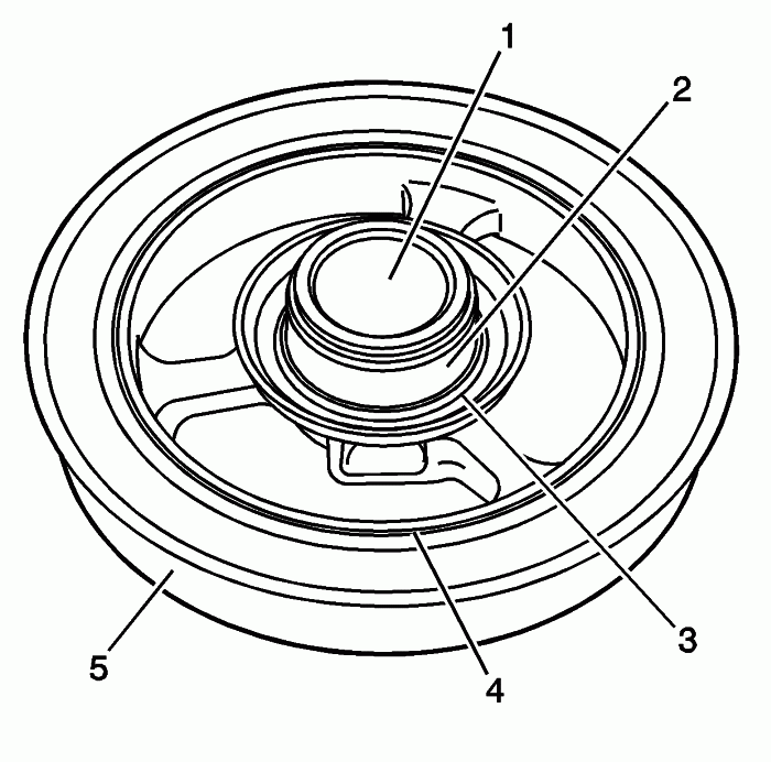
Crankshaft Balancer Cleaning and Inspection
Cleaning Procedure
Clean the crankshaft balancer in solvent that is compatible with the rubber (3).
Caution: Wear safety glasses in order to avoid eye damage.

Dry the crankshaft balancer with compressed air.
Inspection Procedure


Inspect the crankshaft balancer for the following:
- Worn or damaged hub-to-crankshaft surface (1)

- Worn, grooved, or damaged hub seal surface (2)

• A crankshaft balancer hub seal surface with excessive scoring, grooves, rust, or other damage must be replaced.

• Minor imperfections on the hub seal surface may be removed with a polishing compound or fine grade emery cloth.

- Bent, damaged or missing crankshaft front oil seal shield (3)

- Worn, chunking, or deteriorated rubber between the hub and pulley (4)

- Damaged drive belt ribs (5)

Repair or replace the crankshaft balancer as necessary.
IP: Logged
AJxtcman
Member
Posts: 1098
From: Rock Hill SC
Registered: Nov 2006


Feedback score: N/A
Leave feedback

Rate this member

Report this Post04-23-2007 07:43 AM Click Here to See the Profile for AJxtcmanSend a Private Message to AJxtcmanDirect Link to This Post

AJxtcman

1098 posts
Member since Nov 2006
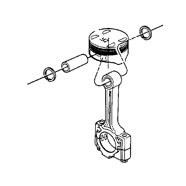
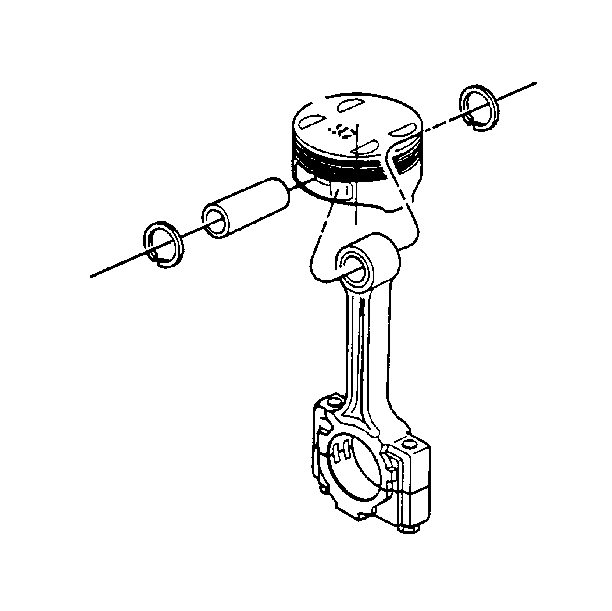
Piston, Connecting Rod, and Bearing Cleaning and Inspection
.
Connecting Rod Cleaning Procedure
• Clean the connecting rods in solvent.

• Dry the connecting rods with compressed air.

Connecting Rod Inspection Procedure
• Inspect the connecting rods for the following:

- Signs of being twisted, bent, nicked, or cracked

- Scratches or abrasion on the rod bearing seating surface

• If the connecting rod bores contain minor scratches or abrasions, clean the bores in a circular direction with a light emery paper. DO NOT scrape the rod or rod cap.

Connecting Rod Measurement Procedure


Measure the piston pin to connecting rod bore using the following procedure:
1.1. Using an outside micrometer, take two measurements of the piston pin in the area of the connecting rod contact.

1.2. Using an inside micrometer, measure the connecting rod piston pin bore.

1.3. Subtract the piston pin diameter from the piston pin bore.

1.4. The clearance should not exceed 0.016 mm (0.0006 in).

If the clearance is excessive, replace the piston pin.
Piston Cleaning Procedure

Important: DO NOT wire brush any part of the piston.


• Clean the piston skirts and the pins with a cleaning solvent.

• Clean the piston ring grooves with a groove cleaner. Make sure the oil ring holes and slots are clean.

Piston Inspection Procedure
• Inspect the pistons for the following conditions:

- Cracked ring lands, skirts, or pin bosses

- Ring grooves for nicks, burrs that may cause binding

- Warped or worn ring lands

- Piston pin retainer grooves for burrs

- Scuffed or damaged skirts

- Eroded areas at the top of the piston

- Worn piston pin bores or worn piston pins

• Replace pistons that show any signs or damage or excessive wear.

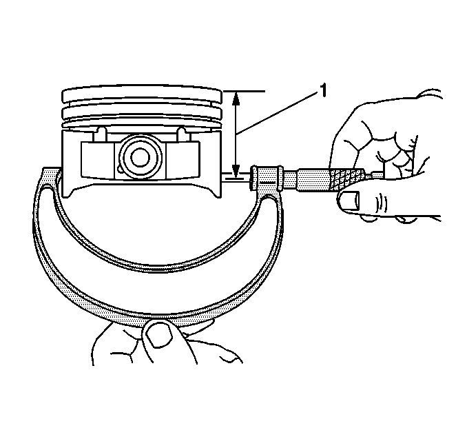
Piston Diameter Measurement Procedure


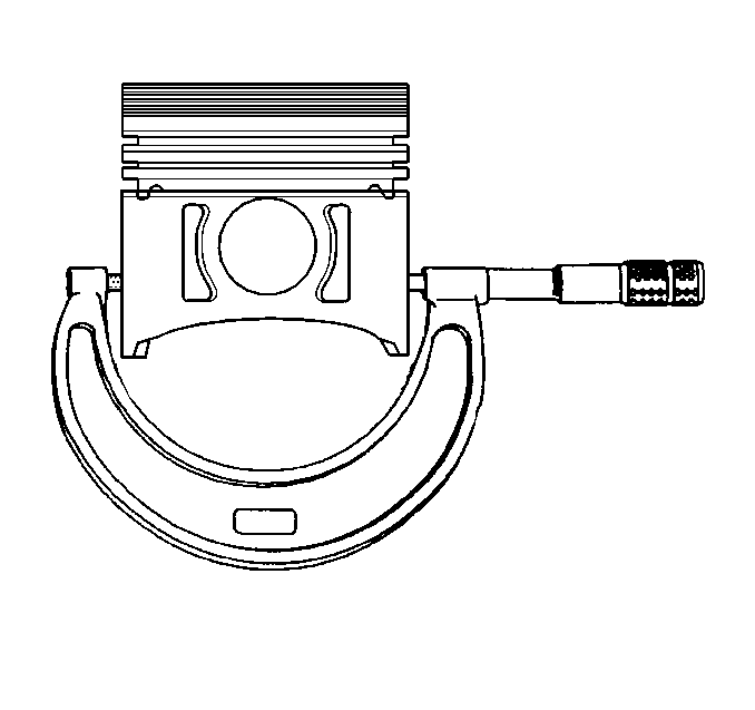
Using an outside micrometer, measure the width of the piston 40 mm below the crown (top) of the piston at the thrust surface which is perpendicular to the centerline of the piston pin (1).
Compare the measurement to the diameter listed in the engine mechanical specfications.
You must replace the piston if any of its dimensions are out of specification. There are no oversized pistons available.
Piston Pin Bore Measurement Procedure


Piston pin bores and pins must be free of varnish or scuffing.
Use an outside micrometer to measure the piston pin in the piston contact areas.
Using an inside micrometer, measure the piston pin bore.
Subtract the measurement of the piston pin bore from the piston pin.
Compare the result with the engine mechanical specifications.
If the clearance is excessive, determine which piece is out of specification and replace as necessary.
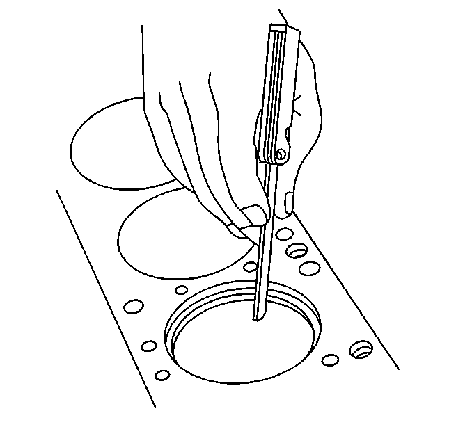
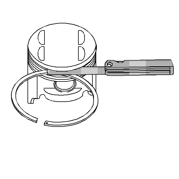
Piston Ring End Gap Measurement Procedure


Place the piston ring in the area of the bore where the piston ring will travel (approximately 25 mm or 1 inch down from the deck surface). Be sure the ring is square with the cylinder bore by positioning the ring with the piston head.
Measure the end gap of the piston ring with feeler gages. Compare the measurements with those provided in the engine mechanical specifications.
If the clearance exceeds the provided specifications, the piston rings must be replaced.
Repeat this procedure for all the piston rings.
Piston Ring Side Clearance Measurement Procedure


Roll the piston ring entirely around the piston ring groove. If any binding is caused by the ring groove, dress the groove with a fine file. If any binding is caused by a distorted piston ring, replace the ring.
With the piston ring on the piston, use feeler gages to check side clearance at multiple locations.
Compare your measurements with those found in the engine mechanical specifications.
If the clearance is greater than specifications, replace the piston rings.
If new new piston rings do not bring the clearance within specification, the piston must be replaced.
When replacing the piston rings, only install re-ring sets that have a 1.2 mm (0.047 in) thick nitrided steel upper compression ring and multi-piece oil rings. The top compression ring may be installed with either side up. There is a locating dimple on the 2nd compression ring near the end for identification of the top side. Install the 2nd compression ring with the dimple facing up.
IP: Logged
AJxtcman
Member
Posts: 1098
From: Rock Hill SC
Registered: Nov 2006


Feedback score: N/A
Leave feedback

Rate this member

Report this Post04-23-2007 01:54 PM Click Here to See the Profile for AJxtcmanSend a Private Message to AJxtcmanDirect Link to This Post

AJxtcman

1098 posts
Member since Nov 2006

Piston Selection
.
Tools Required
J 8087 Cylinder Bore Checking Gauge


Important
Measurements of all components should be taken with the components at normal room temperature.

For proper piston fit, the engine block cylinder bores should not have excessive wear or taper.

A used piston and pin set may be reinstalled if, after cleaning and inspection, they are within specifications.


Inspect the engine block cylinder bore.
Inspect the piston and pin. Refer to Piston, Connecting Rod, and Bearings Clean and Inspect .
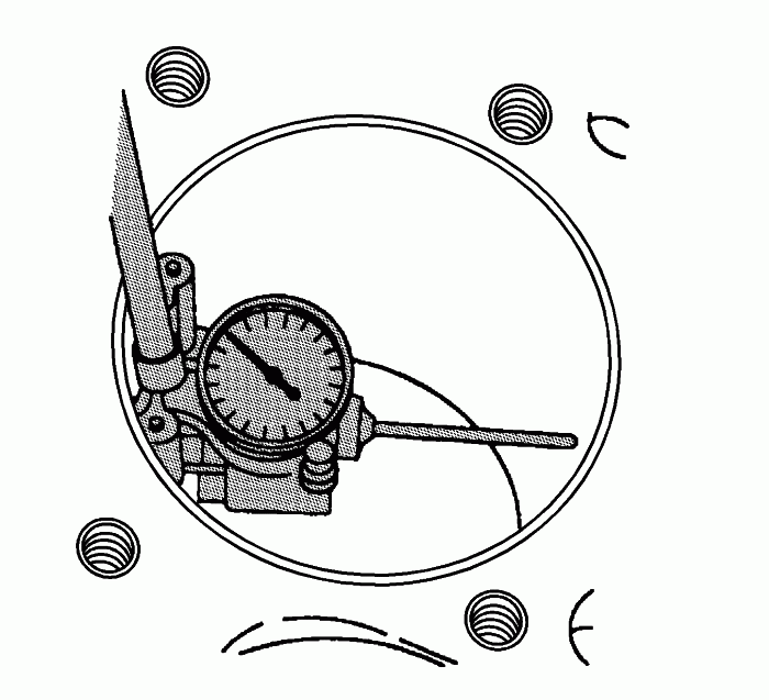
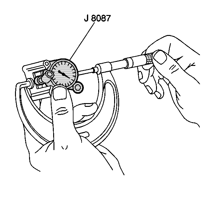
Use the J 8087 and measure the cylinder bore diameter. Measure at a point 64 mm (2.5 in) from the top of the cylinder bore.


Measure the J 8087 with a micrometer and record the reading.


With a micrometer or caliper at a right angle to the piston, measure the piston 11 mm (0.433 in) from the bottom of the skirt.
Subtract the piston diameter from the cylinder bore diameter in order to determine piston-to-bore clearance. Refer to Engine Mechanical Specifications .
If the proper clearance cannot be obtained, select another piston and measure the clearances.
When the piston-to-cylinder bore clearance is within specifications, permanently mark the top of the piston for installation into the proper cylinder.
IP: Logged
AJxtcman
Member
Posts: 1098
From: Rock Hill SC
Registered: Nov 2006


Feedback score: N/A
Leave feedback

Rate this member

Report this Post04-23-2007 01:56 PM Click Here to See the Profile for AJxtcmanSend a Private Message to AJxtcmanDirect Link to This Post

AJxtcman

1098 posts
Member since Nov 2006
Camshaft Intermediate Drive Shaft Cleaning and Inspection
.

Cleaning Procedure
Clean the camshaft intermediate drive shaft in solvent.
Caution: Wear safety glasses in order to avoid eye damage.

Dry the camshaft intermediate drive shaft with compressed air.
Inspection Procedure


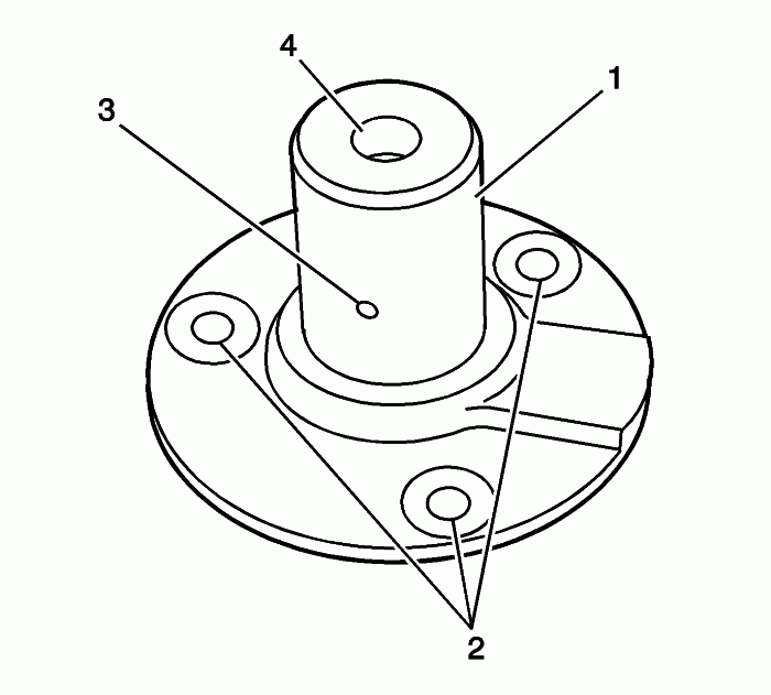
Inspect the camshaft intermediate drive shaft for the following:
• Worn or damaged hub-to-camshaft intermediate drive shaft sprocket bearing surface (1)

• Cracks or damage to the camshaft intermediate drive shaft fastener holes (2)

• Restrictions to the oil passage (3)

• Damaged or stripped thread (4)

Repair or replace the camshaft intermediate drive shaft as necessary.
IP: Logged
AJxtcman
Member
Posts: 1098
From: Rock Hill SC
Registered: Nov 2006


Feedback score: N/A
Leave feedback

Rate this member

Report this Post04-24-2007 06:53 AM Click Here to See the Profile for AJxtcmanSend a Private Message to AJxtcmanDirect Link to This Post
Cylinder Head Cleaning and Inspection

Tools Required


• J 8001 Dial Indicator Set

• J 8358 Carbon Removal Brush

• J 28410 Gasket Scraper (Aluminum Components)

Visual Inspection Procedure
Inspect the cylinder head for the following:
- Cracks, damage or pitting in the combustion chambers .

- Scoring of the camshaft bearings and/or the journals. If the camshaft bearing journals appear to be scored or damaged, you must replace the cylinder head. DO NOT machine the camshaft bearing journals

- Debris in the oil galleries. Continue to clean the galleries until all debris is removed.

- Coolant leaks or damage to the deck face sealing surface. If coolant leaks are present, measure the surface warpage as described under Cylinder Head Resurfacing.

- Damage to any gasket surfaces

- Damage to any threaded bolt holes

- Burnt or eroded areas in the combustion chamber

- Cracks in the exhaust ports and combustion chambers

- External cracks in the water chamber

- Restrictions in the intake or exhaust passages

- Restrictions in the cooling system passages

- Rusted, damaged, or leaking core plugs

If the cylinder head is cracked or damaged, it must be replaced. No welding or patching of the cylinder head is recommended.
Cleaning Procedure
• Clean all cylinder head surfaces with non-corrosive solvent.

• Blow out all the oil galleries using compressed air.

• Remove any carbon deposits from the combustion chambers using the J 8358 .

• Clean any debris or build-up from the lifter pockets.

• Inspect the cylinder head again for the items noted under Visual Inspection.

Flatness Measurement Procedure


Clean any remaining head gasket material from the cylinder head face using the J 28410 .
Place a straight-edge diagonally across the cylinder head face surface.
Measure the clearance between the straight-edge and the cylinder head using a feeler gage at four points along the straight-edge.
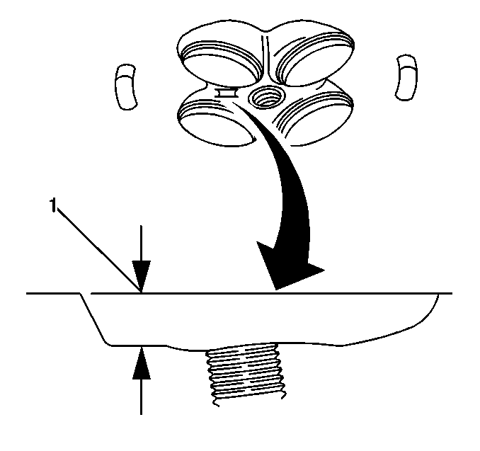
- If warpage is less than 0.05 mm (0.002 in), the cylinder head surface does not require resurfacing.

- If the warpage is between 0.05 mm and 0.2 mm (0.002 in and 0.008 in), you must resurface the head.


If resurfacing is required, the dimension between the combustion chamber gauge pad and the deck surface (1) must be at least 10.5 mm (0.413 in).
Valve Guide Measurement Procedure


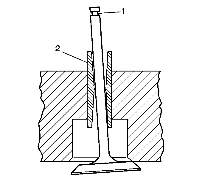
Measure the valve stem(1)-to-guide(2) clearance as follows:
- Excessive valve stem-to-guide clearance may cause an excessive oil consumption and may also case a valve to break. Insufficient clearance will result in noisy and sticky functioning of the valve and will disturb the engine assembly smoothness.

- Clamp the J 8001 to the cylinder head at the camshaft cover rail.

- Locate the dial indicator so that the movement of the valve stem from side to side (crossways to the cylinder head) will cause a direct movement of the indicator stem. The dial indicator stem must contact the side of the valve stem just above the valve guide.

- Drop the valve head about 1.6 mm (0.0064 in) off the valve seat.

- Use light pressure when moving the valve stem from side to side in order to obtain a clearance reading.

If the clearance for the intake valve is greater than 0.11 mm (0.0045 in) and a new standard diameter valve stem will not bring the clearance within specifications, the cylinder head must be replaced.
If the clearance for the exhaust valve is greater than 0.12 mm (0.005 in) and a new standard diameter valve stem will not bring the clearance within specifications, the cylinder head must be replaced.
Valve guide wear at the bottom 10 mm (0.39 in) of the valve guide is not significant to normal operation.
IP: Logged
AJxtcman
Member
Posts: 1098
From: Rock Hill SC
Registered: Nov 2006


Feedback score: N/A
Leave feedback

Rate this member

Report this Post04-24-2007 06:58 AM Click Here to See the Profile for AJxtcmanSend a Private Message to AJxtcmanDirect Link to This Post

AJxtcman

1098 posts
Member since Nov 2006
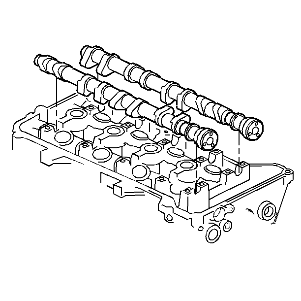
Camshaft and Bearings Cleaning and Inspection
.
Tools Required
J 7872 Magnetic Base Dial Indicator Set


Inspect the camshaft journals, lobes and bearings for the following conditions:
- Excessive scoring or pitting

- Discoloration from overheating

- Deformation from excessive wear, especially the camshaft lobes

If any of the above conditions exist on the camshaft, replace the camshaft.
If any of the above conditions exist on the camshaft bearings, replace the cylinder head.


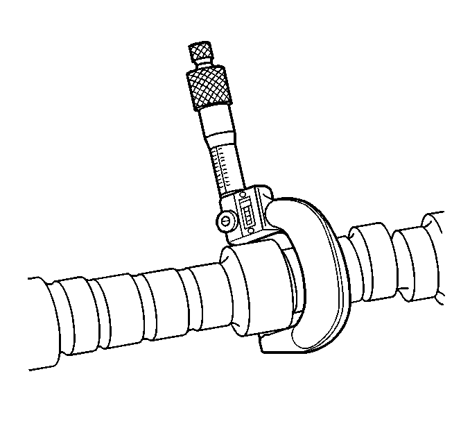
Measure the camshaft journals for diameter and out-of-round using an outside micrometer.
- If the diameter is smaller than 26.948 mm (1.061 in), replace the camshaft.

- If the out-of-round exceeds 0.022 mm (0.0009 in), replace the camshaft.

Install the camshaft bearing cap in the cylinder head without the camshaft.
Measure the camshaft bearings using an inside micrometer.
Subtract the camshaft journal diameter from the bearing diameter. This will provide the running clearance. If the running clearance exceeds 0.041-0.085 mm (0.0016-0.0033 in) and the camshaft journals are within specification, replace the cylinder head.


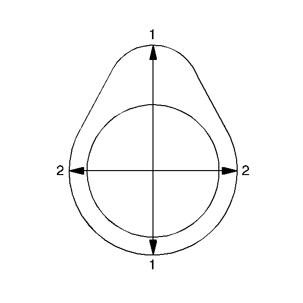
Measure the camshaft lobes for wear using the following procedure:
With the camshaft supported in V-blocks, set up the J 7872 with the indicator tip on the base circle of the camshaft lobe.
Rotate the camshaft until the indicator tip is at the highest point on the lobe. This reading is the lift(1) of the camshaft lobe.
The specifications for lift are as follows:
RPO LD8 - VIN Y


• Intake camshaft lift: 8.6 mm (0.339 in).

• Exhaust camshaft lift: 8.6 mm (0.339 in).


RPO L37 - VIN 9


• Intake camshaft: 9.4 mm (0.370 in).

• Exhaust camshaft: 8.6 mm (0.339 in).

If the indicated measurement is significantly lower than these specifications, replace the camshaft or engine performance will be reduced.
IP: Logged
AJxtcman
Member
Posts: 1098
From: Rock Hill SC
Registered: Nov 2006


Feedback score: N/A
Leave feedback

Rate this member

Report this Post04-24-2007 07:13 AM Click Here to See the Profile for AJxtcmanSend a Private Message to AJxtcmanDirect Link to This Post

AJxtcman

1098 posts
Member since Nov 2006
Camshaft Timing Drive Components Cleaning and Inspection
Cleaning Procedure
Clean all the following components with solvent:
- Camshaft sprockets

- Intermediate sprocket

- Crankshaft sprocket

- Primary timing chain

- Secondary timing chains

- Primary timing chain guide

- Secondary timing chain guides

- Primary timing chain shoe

- Secondary timing chain shoes

- Primary timing chain tensioner

- Secondary timing chain tensioners

- Timing component fastening bolts

Caution: Wear safety glasses in order to avoid eye damage.

Dry the timing components with compressed air.
Visual Inspection

Camshaft Sprockets
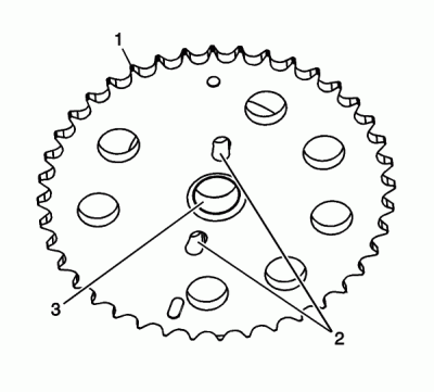


Inspect the front of the left exhaust and intake camshaft sprockets for the following:
- Sprocket damage (1)

- Camshaft locating pin hole damage (2)

- Mounting bolt hole damage (3)
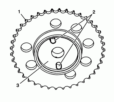


Inspect the back of the left exhaust and intake camshaft sprockets for the following:
- Sprocket damage (1)

- Camshaft locating pin hole (2)

- Camshaft seating/sealing inner hub flange damage (3)
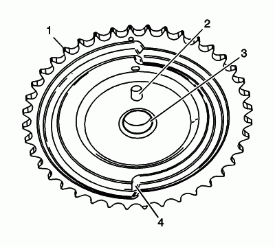


Inspect the front of the right exhaust camshaft sprocket for the following:
- Sprocket damage (1)

- Camshaft locating pin hole damage (2)

- Mounting bolt hole damage (3)

- Camshaft position sensing ring damage (4)
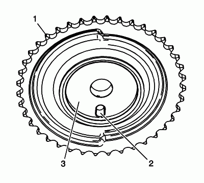


Inspect the back of the right exhaust camshaft sprocket for the following:
- Sprocket damage (1)

- Camshaft locating pin hole (2)

- Camshaft seating/sealing inner hub flange damage (3)
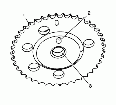


Inspect the front of the right intake camshaft sprocket for the following:
- Sprocket damage (1)

- Camshaft locating pin hole damage (2)

- Mounting bolt hole damage (3)
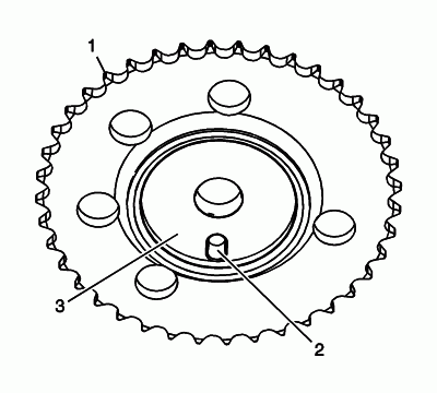


Inspect the back of the right intake camshaft sprocket for the following:
- Sprocket damage (1)

- Camshaft locating pin hole (2)

- Camshaft seating/sealing inner hub flange damage (3)

Replace a damaged camshaft position actuator.

Intermediate Sprocket
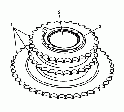


Inspect the front of the intermediate sprocket for the following:
- Sprocket damage (1)

- Bearing bore damage (2)

- Thrust surface damage (3)
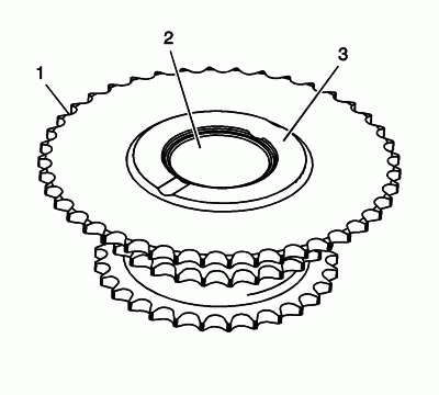


Inspect the back of the intermediate sprocket for the following:
- Sprocket damage (1)

- Bearing bore damage (2)

- Thrust surface damage (3)

Replace a damaged intermediate sprocket.

Crankshaft Sprocket
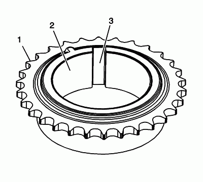


Inspect the intermediate sprocket for the following:
- Sprocket damage (1)

- Bore damage (2)

- Keyway damage (3)

Replace a damaged crankshaft sprocket.

Primary and Secondary Timing Chains
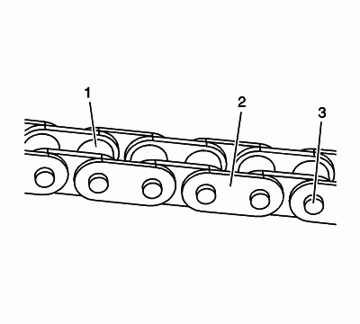


Inspect the primary and/or secondary timing chain for the following:
- Binding or worn rollers (1)

- Loose links (2)

- Loose pins (3)

Replace a damaged primary and/or secondary timing chains.

Primary Timing Chain Guide
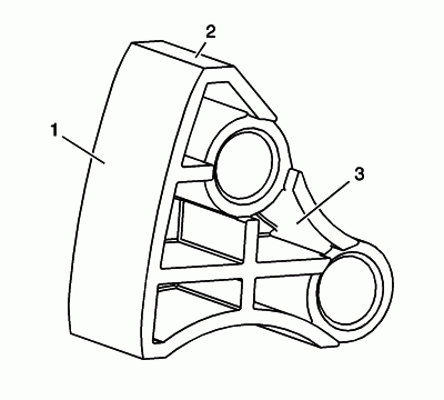


Inspect the primary timing chain guide for the following:
- Worn guide surface (1)

- Cracked or broken guide surface (2)

- Cracked or damaged guide base (3)

Replace a damaged primary timing chain guide.

Secondary Timing Chain Guides
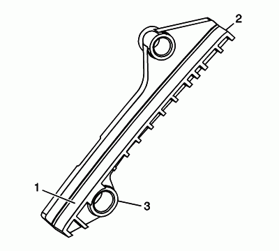


Inspect the secondary timing chain guides for the following:
- Worn guide surface (1)

- Cracked or broken guide surface (2)

- Cracked or damaged guide base (3)

Replace a damaged secondary timing chain guide.

Secondary Timing Chain Shoes
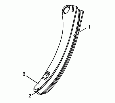


Inspect the secondary timing chain shoes for the following:
- Worn shoe surface (1)

- Cracked or broken shoe surface (2)

- Cracked or damaged shoe (3)

Replace a damaged secondary timing chain shoe.

Primary Timing Chain Tensioner
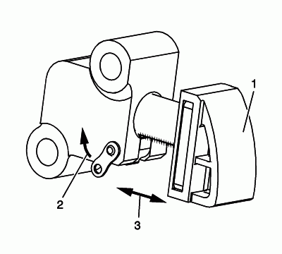


Inspect the primary timing chain tensioner for worn primary timing chain tensioner shoe surface (1).
Inspect the primary timing chain tensioner for locked or binding timing chain tensioner. Release the locking lever (2) and ensure the plunger moves freely (3) in and out of the body of the tensioner.
Replace a damaged primary timing chain tensioner.

Secondary Timing Chain Tensioners
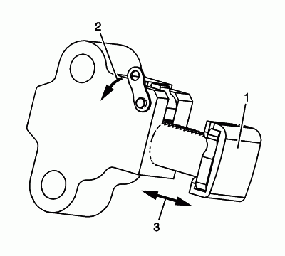


Inspect the secondary timing chain tensioner for damaged plunger-to-shoe contact surface (1).
Inspect the secondary timing chain tensioner for locked or binding timing chain tensioner. Release the locking lever (2) and ensure the plunger moves freely (3) in and out of the body of the tensioner.
Replace a damaged primary and/or secondary timing chain tensioner.

Timing Component Fasteners


Inspect the timing component fasteners.
Replace any damaged timing component fasteners, do not repair.
IP: Logged
AJxtcman
Member
Posts: 1098
From: Rock Hill SC
Registered: Nov 2006


Feedback score: N/A
Leave feedback

Rate this member

Report this Post04-24-2007 07:16 AM Click Here to See the Profile for AJxtcmanSend a Private Message to AJxtcmanDirect Link to This Post

AJxtcman

1098 posts
Member since Nov 2006
Oil Pump Cleaning and Inspection
.
Cleaning Procedure


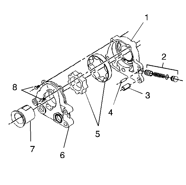
Clean the oil pump components (1-8) with non-corrosive solvent.
Caution: Wear safety glasses in order to avoid eye damage.

Dry the oil pump components with compressed air.
Inspection Procedure


Important: The internal parts of the oil pump are not serviced separately. If wear or damage is noted, replace the entire pump assembly.

Clean the oil pump components with non-corrosive solvent.
Inspect the housing (1) and the cover (6) for cracks, scoring, casting imperfections and damaged threads.
Inspect the gerotor gears (5) for chipping, galling or wear.
Inspect the pressure relief valve (2) for embedded particles and/or damage.
IP: Logged
PFF
System Bot
AJxtcman
Member
Posts: 1098
From: Rock Hill SC
Registered: Nov 2006


Feedback score: N/A
Leave feedback

Rate this member

Report this Post04-24-2007 07:17 AM Click Here to See the Profile for AJxtcmanSend a Private Message to AJxtcmanDirect Link to This Post

AJxtcman

1098 posts
Member since Nov 2006
Intake Manifold Cleaning and Inspection
.
Cleaning Procedure
Important: Do not reuse the intake manifold-to-cylinder head sealing gaskets.


Remove and discard the intake manifold-to-cylinder head gaskets.
Remove any remaining gasket and/or gasket material from the following:
- Throttle body

- Throttle body adapter heater plate

- Intake manifold

Clean the following intake manifold areas in solvent.
- Intake manifold gasket grooves

- Intake manifold passages

- Brake booster hose passage

- EVAP solenoid passage

- PCV vacuum hose passages

- MAP sensor passage

- Throttle body adapter heater plate

Caution: Wear safety glasses in order to avoid eye damage.

Dry the intake manifold and throttle body adapter heater plate with compressed air.
Inspection Procedure
Inspect the following:
- The sealing grommet on the MAP sensor for tears or damage

- The fuel rail mounting tabs for damage

- The intake manifold vacuum passages for debris or restrictions

- The composite intake manifold assembly for cracks or damage

- The areas between the intake runners

- The gasket sealing surfaces and grooves for cracking or damage

- The fuel injector bores for excessive scoring or damage

- The throttle body adapter heater plate for restrictions and/or corrosion

Inspect the following thread bolt inserts for looseness or damaged threads:
- Throttle body

- EVAP solenoid

- EGR pipe

Inspect the intake manifold cylinder head deck for warpage.
Locate a straight edge across the intake manifold cylinder head deck surface.
Insert a feeler gauge between the intake manifold and the straight edge. A intake manifold with warpage in excess of 0.5 mm (0.020 in), must be replaced.
Repair or replace the intake manifold as necessary.
IP: Logged
AJxtcman
Member
Posts: 1098
From: Rock Hill SC
Registered: Nov 2006


Feedback score: N/A
Leave feedback

Rate this member

Report this Post04-24-2007 07:21 AM Click Here to See the Profile for AJxtcmanSend a Private Message to AJxtcmanDirect Link to This Post

AJxtcman

1098 posts
Member since Nov 2006
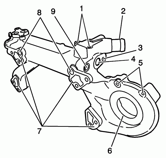
Water Crossover Cleaning and Inspection
Cleaning Procedure
Clean the water crossover in solvent.
Caution: Wear safety glasses in order to avoid eye damage.

Dry the water crossover with compressed air.
Inspection Procedure


Inspect the water crossover for the following:
- Corrosion or damage to the threads for the following connections:

• Engine lift bracket bolt holes (1)

• EGR inlet pipe mounting bolt hole (3)

- Corrosion or damage to the radiator hose outlet (2)

- Corrosion or damage to the water pump drive belt tensioner/shield mounting bolt holes (5)

- Corrosion, damage or restrictions to the seal/gasket sealing surfaces for the following:

• EGR inlet pipe port (4)

• Water pump sealing area (6)

• Water crossover gasket sealing surfaces (7)

- Corrosion, damage or restrictions to the EGR passages (8)

- Corrosion, leakage or damage to the engine coolant plug (9)


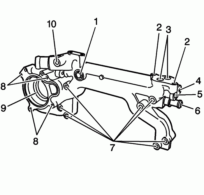
Inspect the water crossover for the following:
- Corrosion, leakage or damage to the engine coolant plug (1)

- Corrosion or damage to the heater hose fitting (6)

- Corrosion or damage to the water crossover bolt holes (7)

- Corrosion or damage to the water pump mounting tabs (9)

- Corrosion, restrictions or damage to the seal/gasket sealing surfaces for the following:

• EGR valve ports (3)

• EGR pipe port (5)

- Corrosion or damage to the threads for the following connections:

• EGR valve mounting bolt holes (2)

• EGR pipe mounting bolt holes (4)

• Heater hose fitting hole (6)

• Water pump cover bolt holes (8)

• Throttle body engine coolant outlet fitting hole (10)

Inspect for damage or sevicability the following components:
- Water pump and seal

- Thermostat and seal

- Water outlet

- Water pump cover and seal

- EGR valve

- Rear engine lift bracket

- Throttle body engine coolant outlet fitting

- Heater hose fitting

- Bolts and fasteners

Repair or replace the water crossover and/or components as necessary.
IP: Logged
AJxtcman
Member
Posts: 1098
From: Rock Hill SC
Registered: Nov 2006


Feedback score: N/A
Leave feedback

Rate this member

Report this Post04-28-2007 10:03 AM Click Here to See the Profile for AJxtcmanSend a Private Message to AJxtcmanDirect Link to This Post
GM's Northstar TimeSert procedure PDF
I can send you a copy also.
http://www.cadillacforums.c...esert-procedure.html

[This message has been edited by AJxtcman (edited 01-29-2008).]

IP: Logged


All times are ET (US)

T H I S   I S   A N   A R C H I V E D   T O P I C
  

Contact Us | Back To Main Page

Advertizing on PFF | Fiero Parts Vendors
PFF Merchandise | Fiero Gallery
Real-Time Chat | Fiero Related Auctions on eBay


Copyright (c) 1999, C. Pennock