Pennock's Fiero Forum
  Technical Discussion & Questions - Archive
  Step-By-Step Audiovox Cruise Control Install with Pics

T H I S   I S   A N   A R C H I V E D   T O P I C
  

Email This Page to Someone! | Printable Version


Step-By-Step Audiovox Cruise Control Install with Pics by joeveto
Started on: 04-04-2009 09:27 PM
Replies: 5
Last post by: IFLYR22 on 04-04-2009 10:26 PM
joeveto
Member
Posts: 287
From: Chicago, IL
Registered: Oct 2008


Feedback score: (2)
Leave feedback

Rate this member

Report this Post04-04-2009 09:27 PM Click Here to See the Profile for joevetoSend a Private Message to joevetoDirect Link to This Post
As the song says "If loving cruise control is wrong, I don't wanna be right..."

Or something like that.

At any rate, I can't live without cruise control. So once I got my 88 Duke running, I ran out and bought an Audiovox electronic cruise control unit. I bought it off of eBay for around $80, which is a great price.

Before the unit even arrived, I began researching to see if anyone else had done this install. I found nothing. So follow along as we do an install...My goal, is to make the process easy enough so that anyone can print this out, follow along, and spend much less time with the installation. To make it as easy as possible, I've included the part numbers as named by Audiovox, and I'll refer to pictures in the Audiovox instructions that pertain to us Fiero folks.

The box itself is pretty compact, given everything that is inside. You'll find each step separately wrapped. I give Audiovox points for trying to cover every possible install, and for providing the parts to do it. However, I have to take a point or two away for not including anything specifically for the Fiero. You'll find that every 80's GM car, save for the Fiero, is specifically listed in the instructions. OK then...


In the above picture you can see most of what is included in the kit. And just about everything you need is included. However, I will add:

20 feet of 18 gauge wire
Solder
Shrink tubing
Electrical tape

As for tools, I used:

Small torx bit - T-15 - to remove the center consoles and glove box
Phillips Screwdriver - to remove the glove box
3/8 socket - to attach the electronic control unit to the engine bay
3/8 ratchet - same
6 inch ratchet extension - same
13mm socket - to attach the Servo Ground Wire to the decklid hinge
Cordless Drill - to drill holes for the Servo unit and to make a hole in the fire wall
Dremel - to smooth out the holes in the fire wall (this may be optional for some, make sure you use a grommet)
Soldering Iron - to solder the connections
Heat gun - to shrink the tubing (you can also use a lighter or a match)
Multimeter - in case you need to check your connections

Step 1.

Remove the air cleaner and the left cover (i.e. not the battery cover, the other one).

You need to do this to access the vacuum hose and the throttle. The cover needs to come off because this is where you're going to mount the control unit. It's also where the stock unit was located.

Step 2 - Attach the secondary throttle cable (exiting the electronic control unit) to the throttle pulley.

In the picture below, you'll see how I installed the throttle cable connection. The electronic unit utilizes a throttle cable that exits the unit itself and needs to be tied into the Fiero's throttle cable system. This step is fairly easy with the adapters provided. There is a black retainer (GM Style threaded snap in cable anchor - part #19) that is nearly identical to the Fiero's primary throttle retainer. This needs to have a small hole drilled into it to allow the secondary throttle cable to pass through.

Attach the snap in cable anchor, with the secondary throttle cable running through it to the throttle cable bracket:


In the above picture, you'll see the two throttle cables, as they are attached. The top cable is the cruise control cable. You can see how I used the fasteners in the kit to attach the cable to the bracket. You can also see how the cable exits the snap in cable anchor (through the hole I drilled) and attaches to the throttle pulley using the kit's Barrel Wire Adaptor (part #30). The barrel of the Barrel Wire Adaptor easily slides into the throttle pulley, just ahead of the primary throttle cable.

Also use Figure #5 in the primary instruction manual for reference.

It's necessary to adapt the barrel wire adaptor to the throttle cable we just added. This is easy using the Bead Chain Coupling (part #24). I just took some needle nose pliars and spread the couplings "wings," inserted the cable, squeezed the wings back together, and was done with it.

Test your connections to the throttle pulley by pulling back a few times on the pulley. Nothing should bind, and everything should stay put.

Step 3 - Attach the vacuum connections

This part is easy.

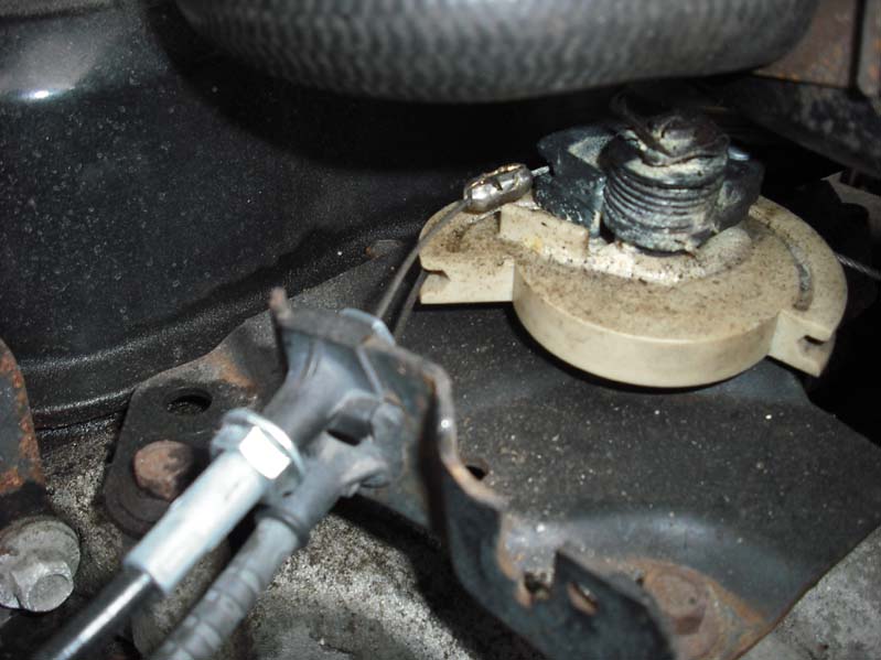
Find the vacuum hose that comes out of the throttle body. Cut it in half. Then, insert the proper vacuum T-Connector (part #8) in between where you cut. From there, connect the long vacuum hose included in the kit (part #10). Take the other end of this hose, and attach it to the vacuum port on the cruise control unit.


If you look to where my finger is pointing, you can see the vacuum attachment.

Route the vacuum hose through the engine compartment in a way that keeps it out of harms way. I also used ties to make sure it stayed put.

Step 4 - Remove the consoles

This step is pretty basic. Remove the shift knob and the ash trays. Unscrew the 4 nuts securing the forward console. Remove the cigarette lighter fascia (two small Torx fasteners), remove the cigarette lighter from the rear console (two screws), then open the glove box, and remove the two screws that hold the rear console in place.

Just an aside: If your plastic console skeleton is forming cracks, as mine was, this is not a bad time to address. I mixed up some two part epoxy and using a toothpick, spread the epoxy into the various cracks that have formed. By the time I was ready to put the console back together, the epoxy had cured and I felt better knowing I stemmed the tide of console destruction.

Step 5 - Drill holes through the firewall for the control units wires

Most of your electrical connections will be made in the interior, so it's important to make the hole large enough for most of the units wires to pass through. I started with a few small holes, then drilled them out larger using a larger bit. Finally, I took my Dremel and I removed any sharp edges, leaving only a hole roughly an inch in diameter.

I chose to drill my holes just to the right (if you're facing out the rear window) of the main wire harness connections. I like this location, because it's covered by the rear console, looks clean, and it will provide for a relatively short path to the Audiovox control unit.

Step 6 - Remove the two small screws from the control unit. Pull off the cover.

Step 7 - Attach the Main Wiring Harness (part #11) to the Servo Assembly (part #1). It just snaps into place.

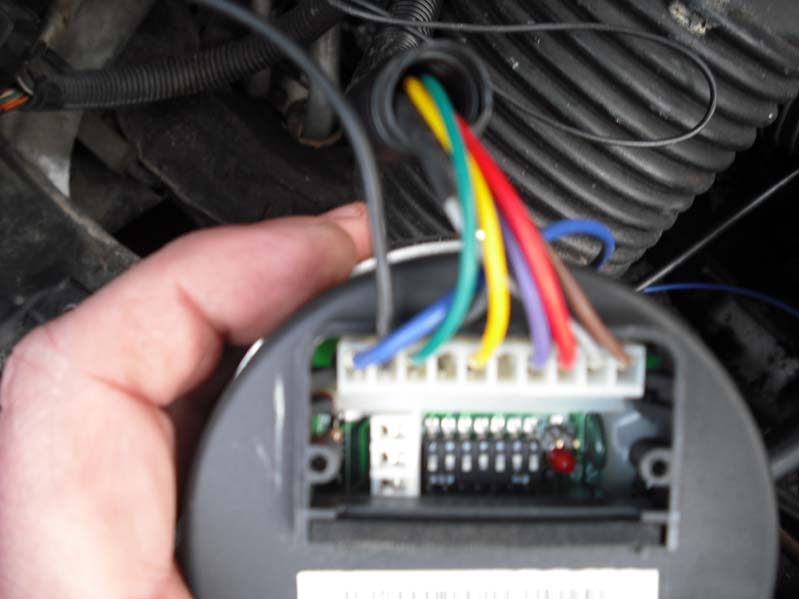
Step 8 - Set the dip switches on the control unit.

This cover conceals the dip switches for the Servo Assembly / control unit. See the picture below...


With the wire harness at the top, the dip switches are: on off on off on off on

This will configure the unit for 4000 PPM (the signal from the VSS), and set the sensitivity for high, for a low powered vehicle (mine is a Duke, I think this will work for the 6 cylinder Fieros as well).

Step 9 - Cut the black Convoluted Tubing (part #6) in half.

Run all the wires, except for the BLUE and BLACK GROUND wire, through the tube and push the tubing back towards the control unit. This should be enough length to protect the wires in the engine bay.

Step 10 - Pass the wires through the hole. ALL of the wires EXCEPT the BLUE tach wire, and the BLACK GROUND wire, need to go through the hole.

Before we continue, I want to make something clear: my intent was to utilize the stock Fiero/GM cruise stalk. I purchased one and installed it (very simple install, pull the old one off, stick the new one in). However, I have not yet made this connection. For this install, I used the included control panel. I wanted to first make sure this was working correctly before continuing to install the stock control stalk. Once this is done, I'll update this post.

Step 11 - Stretch out the wires and route the RED and PURPLE wires towards the drivers foot-well.

The RED and PURPLE wires are the hot and cold brake wires. The RED wire is for the hot brake connection, the pPURPLE is for the cold brake connection (only 12V DC when the brakes are applied)

Because I'm limited to the number of pictures I can post, I'm going to post this and continue in a moment...

------------------
Spent my days with a woman unkind Smoked my stuff and drank all my wine...

[This message has been edited by joeveto (edited 04-05-2009).]

IP: Logged
PFF
System Bot
joeveto
Member
Posts: 287
From: Chicago, IL
Registered: Oct 2008


Feedback score: (2)
Leave feedback

Rate this member

Report this Post04-04-2009 09:28 PM Click Here to See the Profile for joevetoSend a Private Message to joevetoDirect Link to This Post
Here, you can see the connections I made to the brake switch...


The brake switch is best seen on your back, looking up into the foot-well. At the top of the brake pedal, you'll see the white brake switch. If you take a multimeter, the orange wire should show 12V DC at all times. The light blue wire and the white wire, take your pick, will show 12V DC only when the brake pedal is pressed. Try it, it's fun...

The RED wire needs to be connected to the ORANGE wire coming out of the brake switch. As you can see in the photo, I used the blue quick connect. Then, using the same process, connect the PURPLE wire to the LIGHT BLUE wire.

Step - 12 Connect the Fused Wire Switch (part #12) to the main wiring harness (these are the wires coming through the firewall.

This is really pretty easy. The wires coming through the firewall, that need to be connected, are the BROWN, YELLOW, and GREEN wires. These three wires have butt connectors on them, and simply need to be pushed into the the back of the Molex connector (part #12). Just make sure you push them through the correct side, the side into which the RED wire is passing through. Then give each a tug to make sure it's tight. This connector will eventually mate to the connector on the Dash Mounted Control Switch (part #3).

Step -13 Mount the Dash Mounted Control Switch (part #3)

I chose the panel to the lower left of the steering wheel. I separated the lower column cover from the gauge panel (a few Torx screws and a few nuts), ran the wire into this gap, and then reassembled. I did this because I'm only using the dash switch temporarily, and I didn't want to drill any holes into my interior trim. Eventually I will use the stock cruise stalk.

"Mounted" this way, the control switch works just fine.

If you choose not to use the stock stalk, you will most likely want a more permanent fixture. Follow the directions supplied with the unit. The Dash Mounted Control switch comes with a template for your drilling pleasure, and some double sided tape to stick the unit.

Step - 14 Run the wires from the dash switch down below and towards the console.

Step - 15 Ground the switch!

This is important, in that nothing will work without the switch being Grounded. I used the metal bracket to the left of the brake/clutch. It's a thick metal bracket with a hole and makes for a fine ground.

Step - 16 Lengthen the other wires.

The GREEN, YELLOW, and BROWN wires are not long enough, not for our cars. The only way they can work, is if you're going to permanently use the Dash Mounted Control Switch and mount it on the center console. If you want it mounted on the dash, or intend to use the stock cruise stalk, you must lengthen these wires.

To keep things simple, and to maintain the wire coloring, I chose to cut the GREEN, YELLOW, and BROWN wires in the middle. I then soldered in an additional 2 feet of 18 gauge wire and covered my new connections with heat shrink. You can also use electrical tape, but I feel the heat shrink works better.

Step - 17 Connect the main harness to the control switch harness.

Just snap it together.

Step - 18 Connect the ORANGE wire from the fuse-holder to a wire that is hot when the ignition is on. I have an amp in my car that is already connected to a switched 12V DC source. So I used this. If you do not have this, you can tap into your radio power wire. To do this, remove the 4 Torx fasteners that connect the radio faceplate, remove the faceplate, remove the radio, and find the correct wire. I believe it is the RED wire...

Step - 19 Connect the VSS

This was a head-scratcher, but thanks to some online documentation, I got lucky. Please see the picture below.:


What you're looking at, is the C203 connector. It's the clear connector under the rear console. You need to tap into the YELLOW wire for the VSS signal and connect it to the GRAY wire coming from the main wiring harness. This GRAY wire has a spade connector on it and is taped to a BLACK wire as well. We have no use for the BLACK wire. This is saved for the poor folks who have to use a magnet pick-up.

We do not.

I cut back the clear rubber boot from the GRAY wire, and then trimmed the spade connector until it was narrow enough to fit into the slot with the YELLOW wire. I then ran electrical tape around it to secure the connection. Voila! We have a VSS connection.

Ok, now I'm going to start a third post and wrap this puppy up. We're almost done!

[This message has been edited by joeveto (edited 04-05-2009).]

IP: Logged
joeveto
Member
Posts: 287
From: Chicago, IL
Registered: Oct 2008


Feedback score: (2)
Leave feedback

Rate this member

Report this Post04-04-2009 09:30 PM Click Here to See the Profile for joevetoSend a Private Message to joevetoDirect Link to This Post

joeveto

287 posts
Member since Oct 2008
Step - 20 Clean up the wires.

I like to go around with some electrical tape and tie the wires together so that they neat. It's also a good idea to check your work and make sure no wires are hanging by your feet. Make sure you tie up these wires, down in the footwell, as well.

Step - 21 Drill some holes and mount the Servo Assembly (part #1) or what I like to call the main control unit.

Before you do this, turn on the ignition and make sure the control panel lights up when you turn it on. Then, walk out to the back and check the Servo Assembly. Look into where the dip switches are. There is a small red LED. If all your connections are good, this red light will come on with the control panel light. If it doesn't, double check your connections.

Assuming all is lit up as it should, take the two small screws that hold the Servo Assembly cover in place, and replace the cover. Snug down the screws, but not too tight.

Hold the servo unit up to the engine bay, as seen in this photo, scribe some holes, and then drill away.


I used one sheet metal screw (part #4) to hold the unit in place, then I scribed and pilot drilled the other three holes. Once that was done, I ran the other three sheet metal screws in.


Step - 21 Connect the BLACK GROUND Wire from the Servo

I attached it to the decklid hinge, just as the chassis to body ground is done on the other side of the car. This requires a 13mm socket.


Step - 22 The BLUE Tach Wire

Ignore it. You don't need it.

Step - 23 Give it a once over and then take it for a test drive. If anything doesn't work, check your connections.

Then...Button it up and Enjoy!


I hope this helps. If you ever have any questions feel free to PM me.

Cheers!

------------------
Spent my days with a woman unkind Smoked my stuff and drank all my wine...

[This message has been edited by joeveto (edited 04-05-2009).]

IP: Logged
IFLYR22
Member
Posts: 1775
From: Tucson, AZ.
Registered: May 2007


Feedback score: N/A
Leave feedback

Rate this member

Report this Post04-04-2009 10:21 PM Click Here to See the Profile for IFLYR22Send a Private Message to IFLYR22Direct Link to This Post
Nice. I am planning on adding Cruise to my fiero, but haven't gotten around to it.

for those who don't want to scroll at XX-large pictures...


IP: Logged
joeveto
Member
Posts: 287
From: Chicago, IL
Registered: Oct 2008


Feedback score: (2)
Leave feedback

Rate this member

Report this Post04-04-2009 10:25 PM Click Here to See the Profile for joevetoSend a Private Message to joevetoDirect Link to This Post
Thanks a ton for the resize. I couldn't figure out how to do it with my image-host service, and my image software isn't loaded on my new machine yet.

------------------
Spent my days with a woman unkind Smoked my stuff and drank all my wine...

IP: Logged
IFLYR22
Member
Posts: 1775
From: Tucson, AZ.
Registered: May 2007


Feedback score: N/A
Leave feedback

Rate this member

Report this Post04-04-2009 10:26 PM Click Here to See the Profile for IFLYR22Send a Private Message to IFLYR22Direct Link to This Post
your welcome. Nice write up. good detail.
IP: Logged


All times are ET (US)

T H I S   I S   A N   A R C H I V E D   T O P I C
  

Contact Us | Back To Main Page

Advertizing on PFF | Fiero Parts Vendors
PFF Merchandise | Fiero Gallery
Real-Time Chat | Fiero Related Auctions on eBay


Copyright (c) 1999, C. Pennock