Could someone please measure the width between the rear frame rails along the engine centerline? I'd also like to know the distance from the transmission to engine (bellhousing mount flange) to the passenger frame rail and the driver frame rail. I'm building a tube frame rear end and I need to know how wide to make it to interface with the 88' Cradle I have and a 302 SBC with a Getrag and Archie V8 kit.
I have the engine & cradle out of my 88 GT at the moment so I can provide you an accurate distance between framerails at the engine centerline, but only tomorrow as everything's buttoned up for the night. Someone else will have to pipe up for the other measurements. Stay tuned.
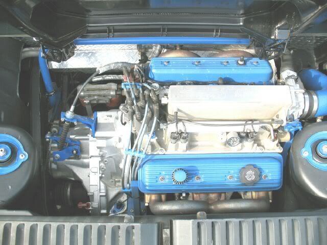
Here's the info you were looking for (keep in mind that these are difficult measurements to make given the differences in height between the various components (ie paralax comes into play so they are as close as I can get them with my crooked eyes!):
Distance between lower framerails at engine centerline (2.8L) = 38" and 5/8" Distance from bellhousing mount to RH lower framerail at engine centerline = 24" and 3/8" Distance from bellhousing mount to LH lower framerail at engine centerline with THM125 Auto = 13"
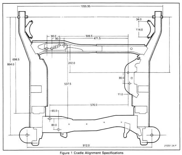
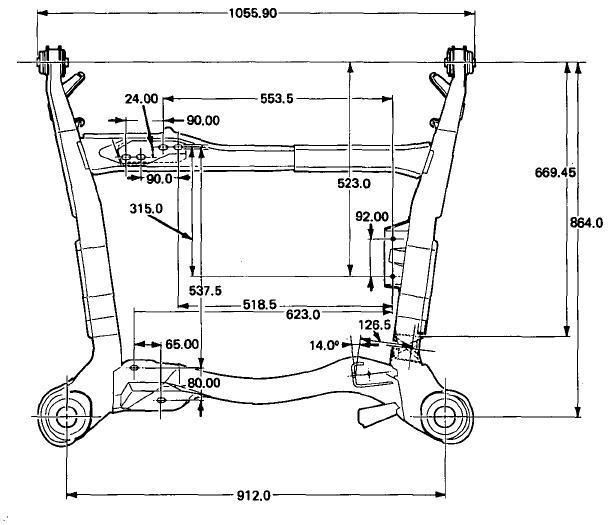
Keep in mind the last dimension applies to the automatic tranny not manual. Also, here are some not-to-scale sketches I drew of my engine/tranny/cradle prior to separating them with some extra details you may find handy. I'm working on a Northstar/F40 swap and am going through the same fun you are, all though I'm fabricating a tubular cradle whereas it sounds like you're remaking the lower framerails. I have additional dimensions logged onto still other sketches if you find that you're still missing something. (Apologies to dial up members as these are large files to capture the details)
IP: Logged
06:49 PM
rourke_87_T-Top Member
Posts: 1347 From: Toronto Ontario Canada Registered: Jan 2009
The distance at crank centerline from engine bellhousing to the driver frame rail is 14 3/8" for my SBC/Getrag w/ Archie kit in my 88 fiero. I can't get to the passenger side measurement due to the waterpump and my cold air intake.
A few things to note: Engine placement front to rear can vary about 1" (mine is further forward than most... and this give me more room due to the frame rails angling out as they get closer to the firewall. On the Archie Manual swaps, the exhaust port for cyliner #7 is very close to being dead center in the chassis side to side (easy to check with the center tabs on the rear deck lid).
If you are making tubular rear framerails, I would make them atleast 2" wider than stock. This will give you plenty of room around the engine/tranny and give you some more options on the belt drive, water pump and accessory drive.
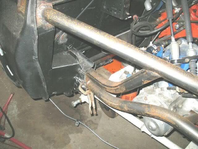
Here is one a friend of my is doing fior his BBC fiero (sorry, only pic I have):
IP: Logged
06:59 PM
CowsPatoot Member
Posts: 2792 From: Skidway Lake, MI Registered: May 2007
I found them on this forum, they are from the GM service manual. I just right clicked to save them, ther is a downloadable copy on the fiero sails secrets, it is listed in Books literature. here is the link. http://www.fierosails.com/fierosecrets.html I am also looking for the blueprints in .pdf from the center pullout section from the "Pontiac Performance Plus" race car construction details book published in September 1983 from the editors of Hot Rod magazine. I have this book but misplaced the center pullout section and did not have a digital copy saved. there is a digital copy of this publication on fiero secret's site but the center section is missing.
IP: Logged
11:12 PM
Apr 29th, 2009
Datsun1973 Member
Posts: 120 From: Fort Worth, TX Registered: Mar 2006
Well i'd love to make them 2" wider but I can't because that would cause the upper links for the suspension to be too short. I was forced to keep the rails about 1/2" wider than a fiero. I think if I use the Streetdreams adapter plate (1/2" wide vs. Archie at 1" wide) and an off engine in-line water pump (~$400) that should solve most of the packaging issues. I ordered one of the plastic 350 engines from P-Ayr and it should be here this weekend so I can start the engine mock up within the frame. Once I get it all mocked up and on the wheels I'll send some pictures out. Just as a teaser it uses 18x10.5 aluminum forged Z06 rear wheels with 305/35R18 rear tires which makes the shocks mount inboard front to back with custom rocker arms and push rods.
IP: Logged
05:04 PM
fieroguru Member
Posts: 12430 From: Champaign, IL Registered: Aug 2003
When you get to the pictures point, I would love to see what you are doing to the back half... might even have to make a road trip since you are only about 4 hrs away.
IP: Logged
07:25 PM
May 1st, 2009
Datsun1973 Member
Posts: 120 From: Fort Worth, TX Registered: Mar 2006
You're more than welcome to come up. I saw your post and wow, nice work. Did you specialize in structures as an ME? I was a propulsion/thermo guy.
I got my plastic engine today and starting looking at the mock up. With 36" between the rear rails (2x2") the SBC should fit with about 1/4" in front of the timing cover. Although I may be able to move the driveline to the passenger side another 1/2". I need to get a new rear trans mount first. I also ordered the adapter plate from Ross at streetdreams today for 181 shipped. I'll let everyone know how that works out. He did offer to build me a custom aluminum flywheel as well for a decent price. I would have gone with Archie from a pure reputation stand point (and i love his shop!) but technically it just wouldn't fit at 1" thick.
FieroGuru, did you also finish your 180 degree headers yet? I am planning to follow your lead there too but I have alot more room since my WB is 96" on the tube frame so I have more room and I think all I need to do is rotate the collectors counter clockwise top looking down and run two 3" pipes straight out the back.
For everyone reading this btw, i'm building a tube frame race car using a lot of fiero parts to keep the cost down.
[This message has been edited by Datsun1973 (edited 05-01-2009).]
IP: Logged
05:29 PM
PFF
System Bot
fieroguru Member
Posts: 12430 From: Champaign, IL Registered: Aug 2003
I was more focused on machine design and manufacturing, but also had a couple of steel structure civil classes as electives!
The 180 headers are waiting for the F40 mockup with the custom adapter plate and the tube cradle... to ensure the collectors will clear the trunk and the tranny shifter. I am hoping to get back to them later this summer.
As things progress I will probably take a roadtrip up to check out your work, and someday you can come on down to see mine.
When it comes time for the flywheel, I have machinist buddies in Mattoon, IL and Battle Ground, IN that both make their own SBC kits and could probably hook you up with a flywheel or other items.
IP: Logged
10:05 PM
May 4th, 2009
Datsun1973 Member
Posts: 120 From: Fort Worth, TX Registered: Mar 2006
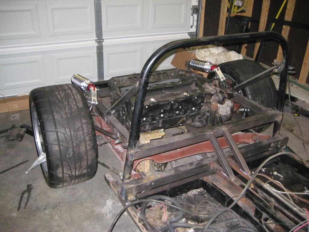
Here is a picture of the rear with the mock up engine and the shocks. Adapter plate comes this week sometime so hopefully I should be able to finish the motor mounts this weekend.
[This message has been edited by Datsun1973 (edited 05-04-2009).]
IP: Logged
07:26 PM
May 5th, 2009
fieroguru Member
Posts: 12430 From: Champaign, IL Registered: Aug 2003
thanks, its a bit of a work in progress trying to adapt something someone else started using old technology to use more modern stuff. It would have been A LOT easier to build a frame from scratch.