I have 6 ½ inches of room below the deck lid to the top of the lower intake to work with.
I need the room below the intake for the discharge plenum, so I need to modify the mounting of the stock fuel rail.
Milling the mounting bosses away and relocating the brackets closer to the rails should do the trick.
With the fuel rail mounting out of the way I will mill a ¼ of and inch off the lower manifold deck.
Once the deck has been milled I will weld two plates one on each side 1 x 2 ½ x however long I need them.
Before the plates are welded a canted hole the size of the runner will be drilled into the plate at each port to extend the runner further to the outside of the blower.
Once the plates are welded I will then add some short tube stubs to the plate for plenum mounting.
Once these simple modifications are done we are ready to set the blower on top for a measurement.
As you can see the red line is the lower intake height before it was milled down a ¼”, this puts the blower right against the deck lid.
A small scoop is probably in order, but I will try to fit in without the scoop. Maybe just a small blister above the throttle body like seem on earlier Eclipse hoods.
Add the plenums and I am in business.
I will be working at it this week and will post with some actual pics when I get started.
Thanks for looking
IP: Logged
11:04 AM
KurtAKX Member
Posts: 4008 From: West Bloomfield, MI Registered: Feb 2002
They let you download a "trial version" for free, which disables the high-level fancy tools after a couple weeks or you can actually the software for keeps for $97. It even spits out handy file formats that you'll be able to send to others with Unigraphics and other popular CAD/CAE softwares. https://www.alibre.com/
[This message has been edited by KurtAKX (edited 02-23-2010).]
IP: Logged
12:24 PM
Scoobysruvenge Member
Posts: 550 From: Richmond Virginia Registered: Apr 2009
I am sick of it to Kurt, but it saves me a lot of time and money… it also lets me throw away bad ideas before I cut and waste any metal on them only to find out they won’t work.
And as for the C-note software goes, I have all but finished the design side of this and am ready to work in aluminum from here on in.
I’ll save the cash for some HP goodies.
Thanks for the interest.
IP: Logged
02:30 PM
Feb 24th, 2010
Scoobysruvenge Member
Posts: 550 From: Richmond Virginia Registered: Apr 2009
BMG Metals is just 6 miles from work so I decided to make a quick lunch time sortie to dig through the drop pile.
As you can see there is a large selection of drops to choose from, the trick is not getting charged too much for it.
More drops…
After a quick look around I came up with a 37” piece of 6061 aluminum tube to use for the plenum runners.
A charge of 1.25$ a foot for the drop and I was 3.75 lighter, they even cut a 6” piece off it for free.
The tube will need to be put in a vice and egged a little to fit the 1 ¼ x 2” holes in the intake, the 1” block should make this a little easier as it can be shaped to accept the tube.
With pipe in hand I was off… back to work…
I will be getting some shop time in tonight and hope to make some progress.
IP: Logged
01:39 PM
Scoobysruvenge Member
Posts: 550 From: Richmond Virginia Registered: Apr 2009
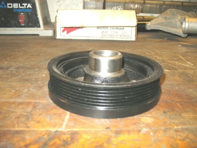
I thought some of you might be curious about the pulley problem…
The blower came with the stock 8 groove pulley and my 3500 has a 6 groove pulley on the balancer… This is a problem…
I could just line it up so that the 8 groove blower pulley contacts on the first six grooves and let it eat…
Blower belt slip is something I want to avoid if I can so I picked this up on Ebay.
It looks a little crusty but it should do the trick as long as it not bent, the seller assures me it is not bent and is good condition other than the surface rust. (we’ll see)
The bore diameter is 1.255 on ford balancers and 1.245 on GM balancers, the length of the bore is also much shorter on the Ford balancer.
At first glance this looks to be a waste of money, but I have a plan…
Cut the hub out of my gm balancer, machine it nice and round and then drill a hole in the Ford balancer the size of the machined GM hub.
Slide them together and then weld them together. Should be a piece of cake and cheap.
As for the rest of the accessories (alternator, tensioner AC comp ect.) I will source them at the local bone yard from stock 8 groove pulleys like on F 150 trucks.
Thanks for looking.
IP: Logged
02:06 PM
Feb 25th, 2010
Scoobysruvenge Member
Posts: 550 From: Richmond Virginia Registered: Apr 2009
Riding home Friday evening I was thinking on the plate design I had begun to fabricate on my last trip to the shop. The thought of how hard it was going to be in retrospect to make six of these ports and get them evenly CC’d was indeed a large order.
I woke Saturday with the problem filling my head with doubt… I got to the shop and looked at the intake intensely for a half an hour or so playing around with some of the angled tubes I had cut.
Before I went the plate route I looked around for some oval tubing that would fit around the port nicely but had not luck.
So I decided to chuck a small piece in the vice and give it a squeeze to see what I could do with it… I started with a small 30 degree scrap.
Setting the piece on the intake looked promising.
A little work with a body hammer and I had a better shape. I will use a wooden form to get a finished oval, but this is fine for now.
With the test piece a success I began to make some more 30 degree cuts at 2.5” long.
The process was going smoothly with 3 of the 6 pieces made and the intake was starting to take shape.
After a little more fab work I had all six pieces cut and ready for the next step.
Laying some of the 3” box I have on top to get a feel for what king of space I will have.
I will not be using the box I will be using the 2.5” tube I have for this, but you get the idea.
The ports on the lower intake will need some material built up around them on two sides… You can see the gap if we look at this photo again.
The next step will be to pull the lower intake for welding, but that will have to wait for my next sortie… Sadly I was out of time again.
Thanks for your interest.
IP: Logged
08:53 AM
KurtAKX Member
Posts: 4008 From: West Bloomfield, MI Registered: Feb 2002
I had a little time last night to remove the lower intake.
Before pulling the intake I took advantage of the rigid mounting and cleaned the runner bosses with a SS wire wheel.
I then removed the valve covers.
A close inspection revealed more evidence that this was indeed a 42,000 mile engine.
A couple of whacks with a rubber hammer and the intake came off nicely.
After some research into oval tubing I found exactly what I needed… The two inch egged in a vice is out and this is in.
This tube is an exact match for the 3500 runner port size. I will cut it at 30 degrees just like I did the 2” pipe. It should eliminate the need for the intake to built up with filler rod and eliminates 90% of the port work I would have had to do using the 2” tube.
15$ a foot! Ouch!
It will be worth the 3 days of waiting for the work/time saved.
I wait….
IP: Logged
10:33 AM
PFF
System Bot
Scoobysruvenge Member
Posts: 550 From: Richmond Virginia Registered: Apr 2009
If so all the piping past the throttle body is considered as part of the plenum.
In my configuration the TB will be mounted to the blower. The air will move through the blower out to the intercooler and back to the logs that feed the lower intake through some short pipes.
Do I need to figure all of this piping, the volume of the intercooler and the blower cavity in my plenum math ??? Or do I just figure the log volumes ???
Anyone ???
IP: Logged
01:39 PM
Mar 3rd, 2010
Scoobysruvenge Member
Posts: 550 From: Richmond Virginia Registered: Apr 2009
I went to the bone yard with my brother yesterday evening, the local one price fits all yard had this 3500 intake manifold for 19.99$
I don’t need it (yet) I hope to start some welding on the intake this week end. I know that when cast aluminum is saturated with oil or some other substance it can bleed into the welds.
I’ll pay the 20 dollar insurance fee, it was a good price and if I screw up I don’t need to wait to find a replacement. (I’ve waited long enough)
When I got home I found the oval tube waiting for me. After opening it I found it to be a very high quality extrusion, not 15$ a foot nice mind you, but a very quality piece.
I will hopefully get started Saturday morning, the welding should go very quickly, it will be the set up of the jig to ensure that the tubes all fit the same.
A piece of angle, some vice grips and some careful measurements should do the trick.
Thanks for the interest.
IP: Logged
07:45 AM
Mar 8th, 2010
Scoobysruvenge Member
Posts: 550 From: Richmond Virginia Registered: Apr 2009
I got home Friday and to my surprise the house was devoid of life… The note on the table read “back late… dinner in oven on low”
I quickly shoveled some casserole into a disposable cup grabbed a plastic spoon a hurried off to the shop before you could say chicken casserole.
I set the chop saw up and got ready to makes some cuts on the expensive oval tubing I purchased.
I set up the first cut at 30 degrees just like the round tube I egged in the vice before.
I made the first cut and everything looked OK
All set I began to make the 30 degree x 3” with a flat opposite of the angle cut.
With all six made it was time to move to the next step.
A quick clean up with a die grinder and I was ready to test fit the runners.
With every thing looking good I used a piece of angle iron and some vice grips to mock up the runners…
With everything clamped up I was ready to get it to the bench and start tacking it together when I discovered we were out of argon.
This was a terrible thing because I wasn’t sure if I could find anyone Saturday that was open. I would have to wait and see Saturday morning as it was already late Friday evening…
IP: Logged
08:10 AM
Scoobysruvenge Member
Posts: 550 From: Richmond Virginia Registered: Apr 2009
Aaahhh… Saturday morning and the gods were looking down on me with favor… Richmond Oxygen was open half a day… I got my argon early and was back to the shop before nine.
I set the intake up and my bro got ready to do some welding…
A little test welding and we got started…
With both sides tacked it was time to test fit it on the engine.
With the runner tubes welded in place I could now move on to setting up the blower plate now that I had something I could measure for real.
I set up a piece of ½ plate and took some measurements and then took them again.
I began by setting the plate up in the mill and making sure the edge was true by millind a few thousandths off the edge.
Setting the head of the mill at 30 degrees I got to work on making the blower plate.
With the plate cut it was time to fit it up to the runners…
Look at the under side reveals the blower discharge area… it may look like a lot but once the fuel rails are in there it gets tight.
A look with the blower on top shows that two ears will have to be removed on this side…
And no ears removed on the other side.
You can see that the blower is not centered on the engine, but offset toward the transmission side.
This is because the blower needs to sit in the center of the deck lid, not the engine.
The blower is quite long and fits between the vent grills with only a few inches to spare on either side. (pics coming soon)
I could have gone with an M90 which would have been quite a bit smaller physically, but I plan on making some real HP.
The 90 is good for 7-8 lbs of boost at a given RPM, any thing after that and it starts making some serious heat.
The 112 is good to 14 lbs of boost before it starts to make serious heat and 14 lbs is about all your going to get on pump gas anyway.
Throw the intercooler in the equation and this should be a very potent set up.
All out of shop time for the weekend, I will post more as it happens.
Thanks for looking.
IP: Logged
09:01 AM
Scoobysruvenge Member
Posts: 550 From: Richmond Virginia Registered: Apr 2009
As you can see this is tight I may have to lower the blower plate a little to get these to work.
I am unsure whether or not I will weld the plate to the tubes or bolt it to them with a 30* block welded to the runners.
I may have to make it removable to get access to the fuel rails, I will know as soon as I get the exact blower mounting location and the hole cut in it.
The blower has a ¾ lip where the intercooler mounted that will set down into blower plate opening. I will seal the blower from the intercooler flange not the mounting flange of the blower itself.
IP: Logged
10:44 AM
kennn Member
Posts: 272 From: Green Valley, AZ USA Registered: Apr 2006
Excellent documentation of process and procedure. Thanks for sharing. I've thought before that this would probably be the most appropriate manner to achieve excellent horsepower in our cars. However, thinking and doing are not the same. Congrats on doing. I'm watching with interest.
Ken
------------------ '88 Formula V6 '88 GT TPI V8
IP: Logged
11:19 AM
Scoobysruvenge Member
Posts: 550 From: Richmond Virginia Registered: Apr 2009
I think a m90 from a T-Bird would work very well on a 2.8… it blows from the back rather than the bottom and could easily be mounted several inches lower than the bottom discharge style superchargers.
The smaller M62 also comes in many configurations, is physically smaller than the M90 and would be easy to adapt to the 2.8 / 3.4 engines. In fact it is narrow enough that it would probably fit between the lower intake runners without modifying the lower intake
Don’t get me started… I’ve been looking at the 2.8 in the Fiero and thinking of the ways I could easily package a supercharger under the factory deck lid, it would be far less complicated than stuffing the M112 in there. You could even mount it on the trunk side of the block and use the stock intakes blowing through the stock TB.
Let’s see… add a super charger to a bone stock 2.8 and get 40% more HP = 196 HP on the stock components… open up the exhaust a little and you’d be well over 200…
Again thanks for your interest…
IP: Logged
12:42 PM
Scoobysruvenge Member
Posts: 550 From: Richmond Virginia Registered: Apr 2009
Looking at a M112 compressor map we see the 1.9 absolute pressure ratio (about 14 lbs of boost) intersecting at the 12,000 RPM.
I got the 12,000 RPM doing the math for the 3” blower pulley and 6” crank pulley combination that I have now at 6000 engine RPMs
You can see that at the max RPM of my engine I am still easily within the usable heat range of the blower with some room to spare.
Add the intercooler and this combo should make huge power right up to the redline with 14 pounds of boost from the blower.
I could drive the blower to its safe maximum of 14000 RPM and add some boost but, 14 pounds is about as much as I will be able to run on pump gas so what’s the point.
I will need to play around with these numbers a little, but what you see on the map is very close to what you get.
Thanks for looking
IP: Logged
02:13 PM
KurtAKX Member
Posts: 4008 From: West Bloomfield, MI Registered: Feb 2002
Pressure ratio (boost) is the dependent variable in this situation. You need blower speed and engine volumetric to get boost, not the other way around.
IP: Logged
05:43 PM
PFF
System Bot
Mar 9th, 2010
Scoobysruvenge Member
Posts: 550 From: Richmond Virginia Registered: Apr 2009
1.9 absolute is roughly 14 lbs above atmospheric or 14 lbs of boost no equation needed here.
Blower RPM is as you can see on the map 12,000 RPM… Note where these two intersect.
These in combination with CFM place you on the compressor map above.
This shows the efficiency of the blower at a given speed (12,000 RPM), pressure ratio (1.9 absolute or 14 lbs of boost) and the amount of air flow (650 CFM)
This could be for any engine not just mine.
The compressor map shown here in this thread is intended to display how much heat the blower will make at 14 lbs of boost (pump gas limit) with the current pulley configuration I have, not how much boost the blower will make.
I might have missed something here, so if this doesn’t satisfy let me know
Pressure ratio (boost) is the dependent variable in this situation. You need blower speed and engine volumetric to get boost, not the other way around.
I agree with kurt here. On my l67 when i had a 3.4 pulley I was running around 10psi, I let the engine breath a little better,I put high ratio rockers on and it dropped to 7-8 psi. Boost is pretty relative, you might get more than 14 psi with a 3" pulley if your heads can't flow it.
IP: Logged
01:04 PM
KurtAKX Member
Posts: 4008 From: West Bloomfield, MI Registered: Feb 2002
1.9 absolute is roughly 14 lbs above atmospheric or 14 lbs of boost no equation needed here.
Blower RPM is as you can see on the map 12,000 RPM… Note where these two intersect.
These in combination with CFM place you on the compressor map above.
This shows the efficiency of the blower at a given speed (12,000 RPM), pressure ratio (1.9 absolute or 14 lbs of boost) and the amount of air flow (650 CFM)
This could be for any engine not just mine.
The compressor map shown here in this thread is intended to display how much heat the blower will make at 14 lbs of boost (pump gas limit) with the current pulley configuration I have, not how much boost the blower will make.
I might have missed something here, so if this doesn’t satisfy let me know
Thanks for your input
Here's a new one, since yours is missing bottom axis labels. The blower efficiency map works like this. For a given operating point, you'll know the blower speed. You can see that as resistance at the output increases (pressure ratio increases) the amount of air pushed through will decrease, due to slip past the rotors.
What you don't have a way of knowing yet is what the pressure ratio is, as you only get a pressure ratio from resistance at the blower outlet. This is to say, that if you spun the blower with the bottom disconnected from your intake, even at 12000 RPM, the pressure ratio would be 1:1. If you bolt the blower down to the engine, and then take 3 of the intake rockers off so the blower has to exhaust through only 3 cylinders, your pressure ratio will be astronomically high.
Until you build your motor, you won't know how "deeply it can breathe" so you won't know how much restriction it poses to the outlet of the supercharger, so you won't know a real "boost" number.
The CFM at inlet number is purely a function of blower inlet speed, its not a place where you can input your engine parameters to get a useful boost level.
Of course, boost in psi is really a meaningless number in the grand scheme of things unless you're comparing two identical (ie stock 3800) engines, because as Justin said, the more you do to increase flow, the lower the registered "boost" you will record, even though you are filling the cylinder with more air and making more power.
The "real" measurement of power is either CFM through the MAF or knowledge of injector pulsewidth while knowing injector size. These criterion will tell you how much air and fuel is being burned, and to a large degree, how much power is being made.
IP: Logged
02:53 PM
Scoobysruvenge Member
Posts: 550 From: Richmond Virginia Registered: Apr 2009
Great information as I am new to the supercharger world and still learning, your input is greatly appreciated
The map was purely a tool to look at the heat or efficiency of the blower at Max or close to the maximum potential of the M112 on street gas with my current pulley set up.
Thanks for the input
IP: Logged
03:37 PM
KurtAKX Member
Posts: 4008 From: West Bloomfield, MI Registered: Feb 2002
There are several things that seem to come up in almost any blower conversation… at the top or near the top of list is belt slip.
My 3500 has a 6 groove pulley, I considered swapping the blower pulley to a 6 groove, but after some home work I quickly abandoned that idea.
This means that I will need an 8 groove balancer for the swap. I have several ways to achieve this.
1 get and 8 groove balancer and modify it… I picked this 4.6 for unit up on ebay for a song and 12$ shipping.
I may try to machine the 3500 balancer down to just the crank sleeve then machine the center out of the 4.6 balancer the same size as the crank sleeve from the 3500 and weld them together. Then machine the weight of the balancer down to the same weight as the 3500 balancer.
The second method would be to find an 8 groove balancer ring that will replace the 6 groove. You can have the balancer rebuilt for 115$ and have the new ring bonded to the 3500 balancer.
This would be easiest and I will be making a junk yard sortie to look for just such a balance with an 8 groove ring that I could cannibalize. If one exists that is.
I am researching the viability of this now.
I will be using 8 groove accessories from what ever I can get them off of at the boneyard on the cheap. I will low mount the alternator and AC while custom mounting the accessories I will get a nice 180* wrap on the belt to keep slip to a minimum.
Another problem might be the clearance between the balancer and the frame rail… The 2.8 balancer is already smacked up against it.
So I have a lot of angles to work out and a lot of work to do…
I will post progress as it happens.
Thanks for the input.
IP: Logged
07:50 AM
Scoobysruvenge Member
Posts: 550 From: Richmond Virginia Registered: Apr 2009
My low ball goal is 275 HP for this engine before the blower enters the picture. The stroke and bore from 3.5 to 3.8 , a good tune (via Megasquirt) a free flow exhaust, some quality machining and assembly should put me very close to this number.
The old school mentality is a 9:1 compression for a blower set up on the street from most of what I read from the older established books on the market and lower for serious boost applications.
However some of the newer books and some reprints of older books state that with a good intercooler that compression ratios as high a 10:1 can be used.
I will be ordering custom pistons… so I will be able to dictate the compression ratio.
10:1 would make for more HP and that eager to run feeling from the engine. I am unsure of how high the compression can be in my situation, there are many variables to account for.
I would like to use the stock 9.5:1 or higher if it is feasible, but trying to put 14 lbs of boost to it will probably put the pistons in the 9:1 range. I have some homework to do...
Any info or books you guys may have or know of on this subject would be greatly appreciated.
BHJ wants 440$ for the standard balancer and more to bond an 8 groove pulley to it.
BHJ can go pound sand!
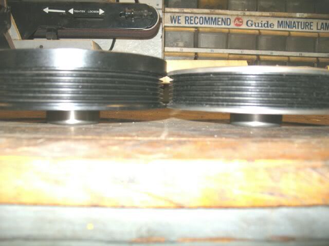
So back to where I was at… oh yea, the 4.6 balancer I purchased measures 3.9 OD the 3500 balancer measures 3.7 OD I will have to wait until I get to the shop to measure the ID of these balancers to see how close the rings are to each other.
I do not know what the 3500 balancer looks like, but the mid 90's 3.1 and 3.4 FWD versions are 6 rib with excess width (I normally turn this portion off for clearance), but you could use this space to turn the additional belt grooves. This balancer will bolt on and can be purchased new on ebay for under $50 (used to be $8 each a couple years back).
IP: Logged
01:44 PM
Scoobysruvenge Member
Posts: 550 From: Richmond Virginia Registered: Apr 2009
This is a great idea... and much better than anything I’ve come up with so far… I will be looking at this very closely tonight to see if I have the extra material on the face of my balancer.
If not I will see if the 3.1 is similar. The local bone yard has balancers for 11.95 you pull.
Thanks very much for your input…
I have been watching your F40 build and think your doing a great job on it. I have been looking into the F40 swap, but I have to finish the engine first.
Thanks again.. I included a positive rating along with my thanks.
IP: Logged
01:54 PM
fieroguru Member
Posts: 12451 From: Champaign, IL Registered: Aug 2003
Making it to the shop I started with a few measurements… starting with the 3500 balancer.
It measured 6 ¾ OD and the inside diameter is not even close to 4.6 balancer I have… the pulley shape is all wrong where it mounts to the balancer… the short and skinny here is, I cannot bond the 4.6 pulley ring to 3500 balancer.
The 4.6 balancer measures 6 7/8 OD and as you just heard the ID isn’t even close.
The weight of the 4.6 balancer is also much greater than the 3500 balancer.
With all that said I will be going with Fieroguru and his idea to use the 3.1/3.4 balancer pictured earlier in this thread. Machining this piece for two extra grooves should be very easy and within my means.
I will try to get to the junkie this weekend to get my hands on a 3.1/3.4 balancer, but they are calling for rain… We will see.
Again I am no expert on anything… well maybe changing my mind… but other than that I have to read, study and confer with the experts on the varied problems I need to solve and I have done some home work on balancers…
What I understand is that diameter is important… this is because as the weight moves further away from the centerline of the crank it changes the “harmonic” a better word may be the dynamic.
The thickness and diameter of the rubber isolator between the inner ring and outer ring determine how much dampening the balancer will have.
Of course whether or not the balancer is neutral balance is important as well, my balancer as well as the 3.1/3.4 are neutrally balanced.
The weight of the balancer is also very important… Just from looks I would say that the 3.1/3.4 piece is the heavier of the two and could machined to remove some weight.
Looks can be deceiving though and if it is lighter weight can also be added.
Every little piece of this project has been a real learning experience. I am always surprised at how something that seems so simple can have so many little details wrapped inside.
More fun to come as it happens.
IP: Logged
08:21 AM
Scoobysruvenge Member
Posts: 550 From: Richmond Virginia Registered: Apr 2009
Another look at the underside of the plate at its current height…
As you can see the red box between fuel rails is the area I have to work with for the discharge plenum… not much 4 1/8 x 3 1/2 inches roughly.
Looking at the space between vent grills I come up 30 inches…
The blower without the snout is 16.5” and ideally set in the center of the trunk lid under the blister on the deck lid…
I am sure at this point that the final blower height will set above the deck lid necessitating a scoop which was in the plans anyway.
This poses another problem though… The balancer sets several inches into the passenger grill or another way of looking at it is the balancer sets under the grill not the deck lid.
The red line in the pick shows roughly where the balancer is located below the grill.
This means that the snout of the blower will protrude into this area and this is a problem…
If the blower sets above the deck lid the snout may also be also set above running into the grill area.
I say may because the blower snout tapers down… the pulley sets about 1.5” lower than the top of the blower.
Now the top deck lid (not including the blister) and the grills set at the same height.
The idea is to try and mount the blower low enough for the snout to pass under the grill not through it.
This will be a challenge and I have no illusions that it will go my way…
However this is not a show stopper… if necessary I will use a jack shaft and a short snout to make it happen.
The snout I have will not work as it is about 2” short for where I want to mount the blower, so regardless I will need a new snout long or short.
What I will be doing next will be to lower the blower plate as low as I can get it… This will reduce the area for the discharge considerably.
How I plan to do this is to use a wedge to make the discharge.
As you can see most of the wedge is beyond the intake and should be easy enough to fabricate.
This leaves me needing to lower the plate another inch or three, now that I have an exact location where the blower will set it is time to cut the hole in the blower plate for the intercooler flange to drop into.
I am also ready to remove the two ears that are in the way of the intake runners posted earlier in this thread for removal.
Should get some trigger time on this, this week end.
IP: Logged
10:15 AM
Scoobysruvenge Member
Posts: 550 From: Richmond Virginia Registered: Apr 2009
All my procrastination has been helpful with keeping mistakes a minimum, but all good things come to and end…
Saturday morning came and it was time to make some progress… I began with a few measurements from the blower discharge flange and writing them down and measuring them again.
With some recorded measurements I set up a piece of ¼” plate in the mill and got to work on the blower discharge flange.
With a 5 ½” wide piece cut I was ready to move to the next step…
A quick cut long ways down to 14”
With the 5 3/8 x 14” plate cut I test fit it to the bottom of the blower.
Everything looking good I cut a 3 ½” piece for the blower discharge ramp.
With the two pieces cut I played around with the fit and angle.
Sliding it under the blower plate you can see there is ample room and then some for this angle to be reduced allowing the blower plate to be mounted lower.
With all looking well I laid the 3 ½ piece over the blower plate and marked it for machining, adding a ½” to the measurement for the ¼” blower ramp sides I was ready to move on.
I set the blower discharge plate up in the mill trued it and was ready to mill out the blower discharge hole.
With everything set up in the mill I got started with milling out the hole.
With all the milling done I had my blower discharge plate ready for a test fit.
Every thin looked good… A quick layover of the 3 ½ discharge ramp shows a good fit…
Next I set to work on milling the hole in the blower plate itself.
Finishing the blower plate hole I was ready for a test fit.
A quick fit to the bottom of the blower and all was still good.
A lay over on the intake also looked good…
A quick shot with the ramp plate.
A check to make sure the discharge plate will fit through the blower plate shows a tight fit, but still good.
With all that done I trimmed the plate down on both ends within a ¼” of exact (I little material to play with if I need it)
Another test fit… very close to actual size and looking good.
Setting the blower on top shows no ears removed on this side…
And two ears to remove on this side…
I was now time to seal the blower up so I could trim the ears…
One ear removed via sawsawl ( I will mill the rest off later)
The second ear removed…
With both ears removed I set the blower on top…
A close look shows no interference…
A look at the blower discharge flange from the bottom of the plate…
A test fit of the blower ramp shows that the blower can go much lower. I only need 3 ½” for the discharge her I have 8 or 9 inches.
With this I was all out of time for the weekend.
The next step will be to narrow the blower plate another inch to 1.5” this should leave me an inch or so above the deck lid.
I will post it as it happens…. Thanks for looking.
IP: Logged
10:04 AM
Scoobysruvenge Member
Posts: 550 From: Richmond Virginia Registered: Apr 2009
The red line is the height of the original 3500 plenum or 3 inches exactly from the lower intake flange to the top of the plenum…
The 3500 lower intake and plenum measure 9 inches together or plenum = 3” tall and lower intake 6”
Since I won’t be using the 3500 plenum my math will start at the lower intake flanges.
From the lower intake to the deck lid of the Fiero is roughly 6 ½ inches…
I determined this as some of you may remember from earlier in this thread by taking a precision measurement…
This told me that the roof of the deck lid was 2 ½ inches taller than the stock Fiero Plenum…
The 3500 intakes measure 9 inches total and the 2.8 intakes measure 10 inches total.
Now this a little hard to express so others can see where I am headed, but here it goes…
The Fiero plenum is 2.5” lower than the deck lid… This gives me 2.5 inches…
The 3500 plenum sits 1 inch lower than the Fiero piece… This gives me 1 inch more…
So far we have 2.5” + 1” = 3.5” of space… With me so far???
I will not be using the 3500 plenum which is 3 inches tall… This gives me 3 inches more…
2.5 + 1 + 3 inches = 6.5 inches of clearance under the deck lid for my blower.
6 ½ inches of available space for the blower and blower plate.
The blower is well under 6 inches tall, but one ear sitting higher than this at the throttle body flange we will call it 6 inches…
With no blower plate this puts me ½ of an inch below the deck…
If include the blower plate made of ½ inch aluminum I have nothing left, this is if the blower plate were mounted flush to the lower intake…
Now the blower plate has to mounted above the lower intake flanges some to allow for the blower discharge…. What ever this amout ends up is the amout or inches the blower will set above the deck lid..
If we look at this pic again we the blower plate is already below 3” and I feel I can lower it another 1.5” and still have room for the discharge.
The limiting factor is the blower is 8 inches wide the blower plate is 9 ¼ inches wide now meaning I can remove another 1 ¼” from the sides thus lowering the plate further.
So this would put me a modest 1.5 inches above the deck lid and not having to cut or notch any of the supports for the lid (very important for the strength of the lid)
This is the idea in principal anyway…
Thanks for looking.
IP: Logged
11:42 AM
fieroguru Member
Posts: 12451 From: Champaign, IL Registered: Aug 2003
Any plans to lower the engine/transmission to assist in head room for the blower? The center is of the decklid has a bubble up top that you do not have on the sides. Also there will not be much left of the passenger decklid support channel.
You might just want to run w/o a decklid (just keep the portion to cover the trunk) or use glass hatch to show off your work.