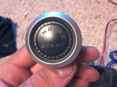
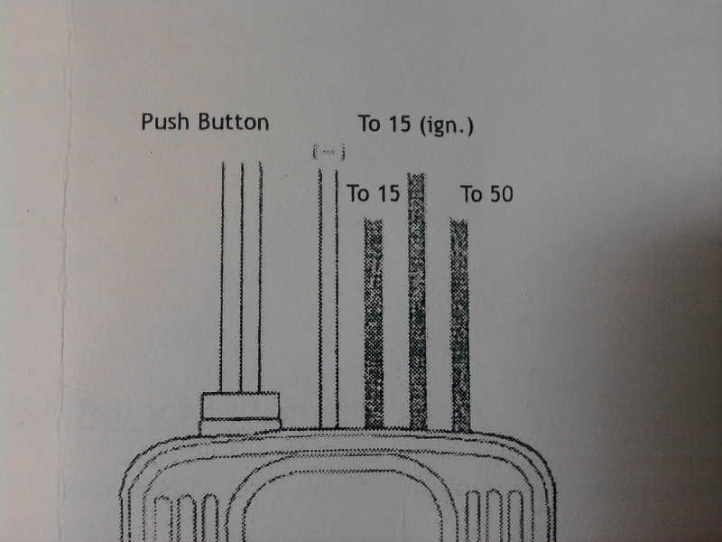
I just bought this button and relay now how to hook it up? the directions are in Chinese and there is more wires than I thought. I have an 86 v6 auto, and want to have to put the key in and then push the button, and the key will not start it by itself. Thanks
pics
IP: Logged
08:01 PM
PFF
System Bot
PerKr Member
Posts: 641 From: Mariestad, Sweden Registered: Nov 2006
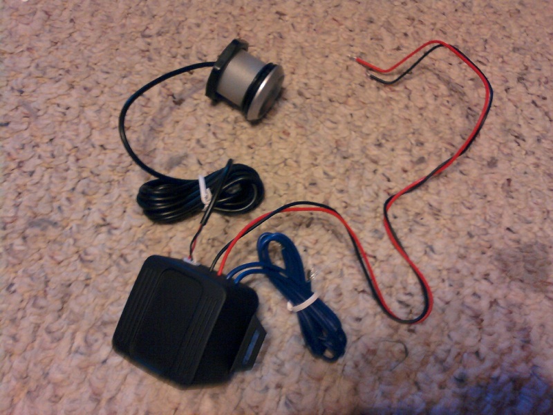
the black wire is ground and the red wire is power for the relay. the blue wires should hook up to the ignition switch so that when the key is turned the relay has a signal pathway then when you push the button the relay gets power to turn the motor over and then disengages. thats they way it should work dotn quote me on it. and i dont know what wires off the top of my head the blue wires should be spliced into. have you tried doing a search for other push button starts?
IP: Logged
08:39 PM
IanT720 Member
Posts: 1703 From: Whitmore Lake, MI Registered: Sep 2010
That makes alot of sense, I have looked but the posts I have found are only for manuals where you need to wire the clutch switch, so I really do not know I think it's a red and yellow wire?
IP: Logged
08:50 PM
phonedawgz Member
Posts: 17091 From: Green Bay, WI USA Registered: Dec 2009
Those two blue wires are WAY too small for the starter wires of your Fiero. You will need to use a high powered relay, with the two blue wires used to activate the relay.
There is the ignition switch - that is actually mounted on the top of the steering column under the dash. It is NOT inside the column, only the key lock is.
At the ignition switch, the FAT red wire gets connected to the FAT yellow wire when you turn the key to start.
The FAT yellow wire runs to either the clutch switch (Manual) or the transmission switch (Automatic). If the clutch is depressed, or the automatic is in park or neutral, the FAT yellow wire is connected to the FAT purple wire that then leads to the starter itself.
So the question is, do you want to just bypass turning the key to start, or the safety switch part of the circuit also?
You DO need a high power relay also. Full sized GM cars of the 90's with 3800 engines used this type of relay quite a bit. Do you have access to a junk yard to obtain such a switch? If so find the relay that has a FAT red wire and a FAT purple wire running to it. The way GM wired these cars up was not to run the starter circuit up to the key and to the safety switch, but instead just run the circuit that controls the relay through all that stuff. The relay itself just connects the wire from the battery (RED) to the wire running to the starter (Purple) when all the conditions are correct.
[This message has been edited by phonedawgz (edited 08-18-2011).]
IP: Logged
10:20 PM
IanT720 Member
Posts: 1703 From: Whitmore Lake, MI Registered: Sep 2010
But your Fiero's starter isn't controlled by a module. It's controlled by running the solenoid wire all the way through the body up to the ignition switch, and then to the safety switch, and then to the starter solenoid.
That is why you have to add the relay.
Most late model cars use the relay and some form of module.
[This message has been edited by phonedawgz (edited 08-18-2011).]
IP: Logged
10:30 PM
IanT720 Member
Posts: 1703 From: Whitmore Lake, MI Registered: Sep 2010
Okay, I think I understand. I do want to keep the key in ignition then push button idea. Can you give me more information on connecting which wire to which? I'm new at electrical.
IP: Logged
10:37 PM
IanT720 Member
Posts: 1703 From: Whitmore Lake, MI Registered: Sep 2010
Yeah - the button is already connected to a relay, but a pansy relay. That relay will then control the voltage to the coil of a relay large enough to control the starter solenoid. Oh btw, if you look at the starter solenoid, it is both a solenoid (It moves the starter pinion gear out to mesh with the flywheel) but also a relay (It connects the positive battery cable to the wire that runs inside the starter motor itself)
A button controlling pansy relay, controlling a large relay, controlling the starter solenoid (relay) thus sending power to the motor part of the starter itself
-----
The word ignition could be used to describe the key controlled switch at the steering column, or the spark producing components of the engine. Yes - if you mean using the large relay to 'bypass' the part of the ignition switch that connects the battery to the wire that runs to the safety switch.
[This message has been edited by phonedawgz (edited 08-18-2011).]
It seems to me there's a lot of assumption about what that black box is. A true push button start does more than engage the starter. With true push button start, you just hit the button, and let it go, and the motor will continue to turn over until it catches. The start module monitors either a tach signal or system voltage to determine if the engine is running. Also, a second push is what kills the engine. I wouldn't even consider trying to hook that thing up using the advice of a bunch of guys who are just guessing, no matter how smart they are.
IP: Logged
04:19 PM
phonedawgz Member
Posts: 17091 From: Green Bay, WI USA Registered: Dec 2009
It's going to need more wires and more buttons to do what you are describing.
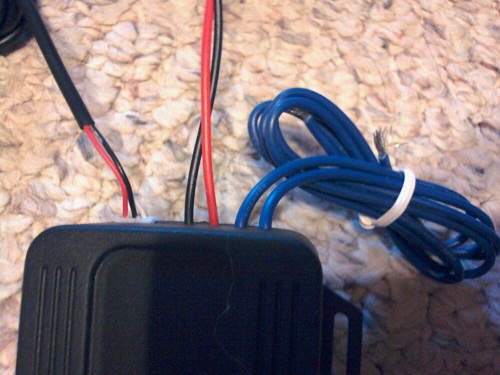
Ian - You can always test it. Hook up a 9v battery to the red and black (Red to positive, Black to negative). Then push the button and listen for the box to click. Assuming it does, you can hook an ohm meter or other continuity reader up to the blue wires and see if you get a closure when the button is pushed.
It's going to need more wires and more buttons to do what you are describing.
Not necessarily, I found a few systems that use only 4 wires for the entire set up. And every start/stop setup I've seen uses only one button. I've been looking, but I haven't found a schematic for this rig yet. I found a few places that sell it, but they all say "professional installation" and don't provide any details on line.
heres a quick solution what company makes it? we can all do a little research and find the english instructions for it. because lord knows how many companies make push buttons for this application.
IP: Logged
09:22 PM
Aug 20th, 2011
phonedawgz Member
Posts: 17091 From: Green Bay, WI USA Registered: Dec 2009
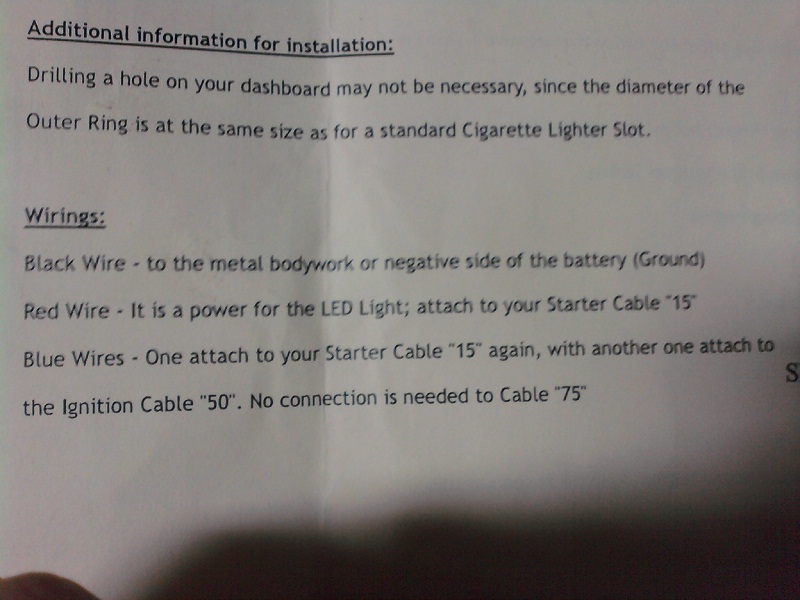
I found an English version and it's not much better here it is exactly as it's written.
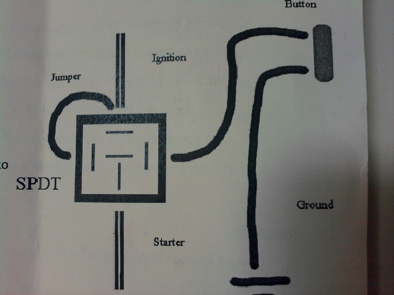
Ensure engine is off Fix pushbutton start to appropriate position Connect black wire to metal bodywork, or negative side of battery (ground) Connect blue wire to the terminal 15 (ign). Behind the ignition switch, with another connects to terminal 50 between the ignition switch (the power path from ign. To the starting motor) Connect red wire to terminal 15 (the power path that passes though ign. ) Fix relay box to appropriate position
[This message has been edited by IanT720 (edited 08-20-2011).]
IP: Logged
06:31 PM
IanT720 Member
Posts: 1703 From: Whitmore Lake, MI Registered: Sep 2010
Those instructions indicate basically what we were saying before
Red - to a switched +12v source
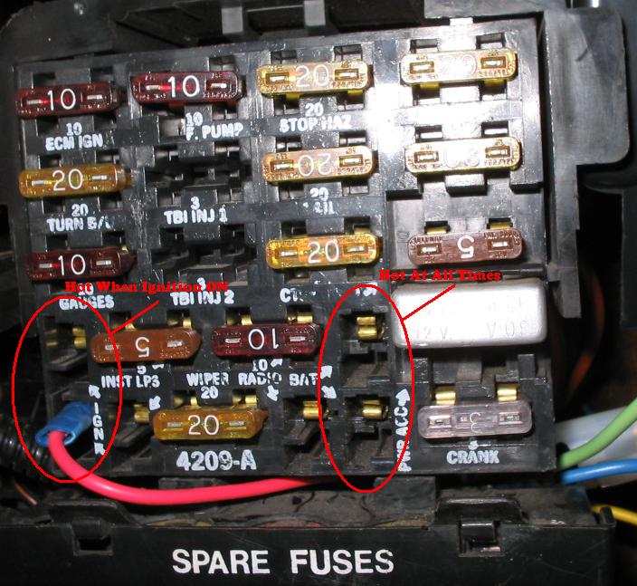
There are places that GM put on your fuse box for this. Attach the red wire where the red wire is attached in this picture.
(if you didn't know it, there are two release latches on the sides of your fuse box so it will swing down into a vertical position)
Black wire to ground
The blue wires are the relay contacts in the push button box. Remember you still need an additional power relay. Using the needed additional power relay - connect one of the blue wires to your +12v source. Connect the other blue wire to the coil of your additional relay. The other coil wire of your additional relay connects to ground.
Then connect the two 'contact' wires of your additional relay - one to the fat red wire of your ignition switch, and the other to the fat yellow wire of your ignition switch.
[This message has been edited by phonedawgz (edited 08-20-2011).]
IP: Logged
07:28 PM
PFF
System Bot
Aug 21st, 2011
IanT720 Member
Posts: 1703 From: Whitmore Lake, MI Registered: Sep 2010