OK, ideas. Disconnect the plug to the dash cluster, disconnect from the sender. Measure the sender wire resistance to ground. Should be open (infinity) Then measure for any low volts running and off.
Other idea. You still have the old temp gage. Get a package of jumper clip leads. (Radio Shack Model: 278-1157 | Catalog #: 278-1157 or the like) Check out the schmo and compare to the dash traces and temp gage to see where the three connections on the meter go to and connect it up right back by the engine using the clip leads to the disconnected sender, power and ground and see what the results are. If it works it will tell you it's still in the wiring somewhere. Does that make since to you?
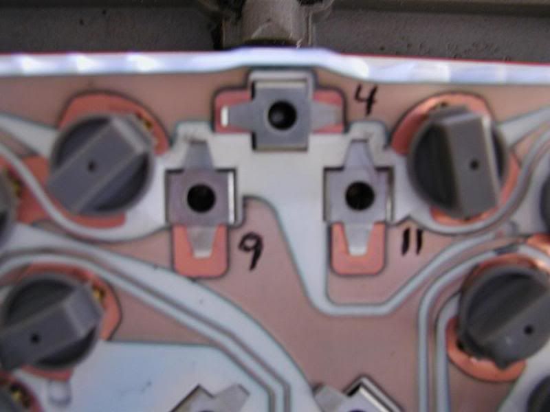
+12 on 9, Ground on 4 and sender on 11.
Photo for gage pin identification.
[This message has been edited by Dodgerunner (edited 11-02-2011).]
IP: Logged
02:10 PM
ltlgt88 Member
Posts: 449 From: round lake, il Registered: Aug 2010
How exactly do I test the wire to ground for resistance...... I think I have a problem with ground to the engine.... so I don't know where to test it to ground and what will.the.meter show.for infinity
Pull the left side plug on the dash. Pull the connector on the temp sender. Put your meter on 20K ohms or higher. With the meter turned on and the test leads just setting there what does the display say. That is infinity (IE no resistance at all). Now touch the two leads together, should be nearly 0 ohms. (dead short).
Now put one lead on a good body ground point and one on either pin 11 of the dash plug or the wire on the sender plug that goes to the temp gage. It really "should" read just like when the meter leads are connected to nothing but there might be just a little reading. Dirt and wire capacitance can sometimes give a reading but should be several 100K. If your getting a low resistance you might either be connected to the temp lamp wire or the wiring is messed up. You might try pulling the temp bulb and see if that made any difference.
Since you don't have the old temp gage you could do the above with the cluster pulled out and connected back in the engine bay as shown. Be a little work but something to try.
Might be worth just pulling the temp bulb and see if your complete problem goes away..
[This message has been edited by Dodgerunner (edited 11-02-2011).]
IP: Logged
04:11 PM
Nov 3rd, 2011
ltlgt88 Member
Posts: 449 From: round lake, il Registered: Aug 2010
i know the wires aren't crossed with the temp light because if i ground the wire of the wire the temp light should be back at the sensor the light comes on without an issue
It has something to do with getting a small voltage through the sensor wire / engine / body ground when the engine is running???
I am just having a tough time wrapping my head around why it only does it when the engine is running???
Got the battery cables and new gauge today, won't be able to work on them tell mid next week, anyone have a good how to on how to change out the cables? especially the + cable?
I will do your test with seeing if there is a reading with everything unplugged and going from the wire to the ground...
To replace the + cable I'd tie a piece of wire or small rope on to the starter end of the old cable. Have a helper pull the old out and use the wire to pull the new one in while the other person pushes from above.
IP: Logged
10:45 PM
ltlgt88 Member
Posts: 449 From: round lake, il Registered: Aug 2010
do you think it is something that might help Dodge?
Replacing the + cable??? I don't really see how it would help since it only provides power to the starter. Power for the rest of the car is provided throught the smaller red wire on the power stud.
My guess is you have a wire somewhere shorting to another wire or some crazy ground loop that might be the problem. Finding it is the trick. That is why I suggested hooking up the temp gage with completely different wires right back at the engine to see if the problem goes away. Then you sure it's in the wire harness somewhere.
Disconnect both ends of the temp sender wire and see if you get any ohm or votage reading on the wire.
Too many cooks spoil the pot, but I'd like to chime in here if you don't mind.
First of all, I don't believe you should be concerned about the 10-15mV you're finding on the sender wire. That's 0.010 - 0.015V. The gauge, being analog isn't remotely capable of sensing that kind of voltage fluctuation. The reason you're seeing that small voltage is because all of the current used by the entire car's electrical system flows from the postivie battery terminal, directly to every device that's operating on dedicated wires, then flows back to the battery using the frame for the return path. The current flow through the frame can cause what's called ground loops, like Dodge suggested earlier. Regardless, the voltage you're measuring is insignificant.
Next, it may help you to understand that the temp gauge only has three wires running to it: a 12V power supply; a solid, steady ground connection, and a variable resistance ground connection through the sender. To see why your gauge is misbehaving, you need to test each of those three circuits to make sure they're acting correctly, and if they are, then your gauge or your sender is at fault. You've already proven your sender is good, so that leaves just the three wires and the gauge.
Start with the 12V power supply circuit: Unplug the big black connector with 12 pins at the back of the instrument panel. Pin 9 should be a pink/black wire;
1. use your multimeter set to DC volts (turn the dial to whatever position is closest to 12V or higher); 2. leave the ignition OFF, and place the red lead from the meter on pin 9 and the black lead to a known good ground like some shiny metal. You should get zero volts; 2a. If you get more than zero volts, stop here and post that information; 3. If you get zero volts, then turn the ignition to RUN (engine off) and you should get 12V (or whatever your battery voltage is). 3a. If you don't get 12V, then stop here and post that info; 4. If you get 12V, then start the car and you should get about 14V (or whatever your alternator puts out). 4a. If you don't get 14V, then stop here and post that info; 5. If you do get 14V, then your power circuit is working correctly, turn the engine and ignition to OFF. Move onto the next phase.
Next up is to test the solid ground wire.
6. set your multimeter to ohms on the 200 ohm range (or less). 7. leave the black lead connected to your known good ground and place the red lead on pin 4 of the instrument panel connector (should be a black wire); 8. You should get 0 ohms or very close to it; 8a. If you get more than say several milliOhms, then stop here and post that info; 9. If you get zero ohms, then turn the multimeter to the 12V range, start the car, and measure the voltage with the two leads as in step 7. 9a. If you get more than 0 volts (or at most several milliVolts) then stop here and post that info; 10. If you get 0 volts (or at most several milliVolts), then the solid ground wire is good and there is no ground loop on that wire. Turn off the car. Move to the next phase.
Next phase is to check whether the gauge pegging problem was modified correctly and completely. Because someone else has done the modification, you had better do a few tests to make sure it was done right:
11. Take you mulitmeter and set it to ohms (200 range); 12. Unplug the sender in the engine bay and note the pin away from the side notch in the connector as Phonedawgz pointed out earlier; 13. Place one meter lead on the pin noted in step 12, and the other on pin 11 (green wire) of the instrument panel connector; 13a. If you get anything other than zero ohms (or several milliOhms), then stop here and post that info; 14. If you get zero or several milliOhms, then the conversion was done correctly, move onto the next phase;
Test the signal wire:
15. set your multimeter to ohms on the 200 ohm range (or less). 16. connect the black lead to your known good ground and place the red lead on pin 11 of the instrument panel connector (black wire); 17. You should get infinite ohms (make sure the sender is still unplugged); 17a. If you get less than infinite ohms, then your sender wire is either improperly spliced onto a another circuit wire, or it is grounding out on the frame somewhere; 18. If you get infinite ohms, then turn the multimeter to the 12V range, start the car, and measure the voltage with the two leads as in step 16. 18a. If you get more than 0 volts (or at most several milliVolts) then stop here and post that info; 19. If you get 0 volts, then the sender wire is good and there is no ground loop on that wire. Turn off the car.
If you've gotten this far, then the only remaining variable is the gauge itself, or perhaps the printed circuit board on the back of the instrument pod. Post what you find if you get this far. Good luck.
Next phase is to check whether the gauge pegging problem was modified correctly and completely. Because someone else has done the modification, you had better do a few tests to make sure it was done right:
11. Take you mulitmeter and set it to ohms (200 range); 12. Unplug the sender in the engine bay and note the pin away from the side notch in the connector as Phonedawgz pointed out earlier; 13. Place one meter lead on the pin noted in step 12, and the other on pin 11 (green wire) of the instrument panel connector; 13a. If you get anything other than zero ohms (or several milliOhms), then stop here and post that info; 14. If you get zero or several milliOhms, then the conversion was done correctly, move onto the next phase;
At step 13 i am getting no change in any reading on my meter, it sits there as if i didn't connect it to anything.... I had to use an extension wire that i made for my meter because it wouldn't stretch that far.
quote
Originally posted by Dodgerunner
Now put one lead on a good body ground point and one on either pin 11 of the dash plug or the wire on the sender plug that goes to the temp gage. It really "should" read just like when the meter leads are connected to nothing but there might be just a little reading.
when i do this i get no reading either just as you stated Dodge.
I just got a replacement board from someone because the old one was torn, tried the brand new gauge i just got from the FS today with everything hooked up and still after running for a little less than 5 min the temp gauge was going slowly up then just took off and went all the way to the right still
Seems like once the temp of the engine gets to a certain temp is when the gauge starts to want to peg, it doesn't do it right at start up but once the engine becomes a little warm.
I went back and checked the wiring of the temp guage fix that i did too...the only thing i did was connect the 2 light green wires coming out of the harness together, i did not connect the other one to the light for the light test part.
Dodgerunner i did remove the bulb for the temp light and nothing different happened.
I ran a test wire from the sensor in the engine outside the car to the all the way to dash and replaced it in pin 11 spot and and still I was getting the same reactions!
what else could it be???
[This message has been edited by ltlgt88 (edited 11-05-2011).]
At step 13 i am getting no change in any reading on my meter, it sits there as if i didn't connect it to anything.... I had to use an extension wire that i made for my meter because it wouldn't stretch that far.
Just to be sure you did this step correctly, you were supposed to touch one lead on the disconnected connector pin, not the actual sender pin. Did you do it the correct way? If so, then the gauge pegging fix wasn't done correctly or there is a break in the sender wire between the sender and the instrument panel connector. Since you've already bypassed the sender wire in your last post, and it still didn't work correctly, then I'd suspect that the pegging fix wasn't done correctly and is causing your problem.
Scroll down to the wiring schematics on this website page www.fierosails.com/tempgage.html to where it shows the "before and after" configurations of the wiring fix. Use your mulitmeter set to ohms and test each wire end-to-end to determine if the wires are indeed where they're supposed to go in the "after" diagram. If you're not sure how to do that, then I can post another step by step for you.
IP: Logged
12:45 PM
ltlgt88 Member
Posts: 449 From: round lake, il Registered: Aug 2010
no i didn't test that correctly, i was testing it to the actuall sender, when i test it to the pigtail for the sender i do get a "0" reading
I also was just looking at my dash and noticed a couple bulbs were dead, and changed those out, still no change in the temp reading,
however though the one below the right trun signal that does not have a lens that says anything lights up? i remember reading somewhere that this shows a bad ground? could this have any effect on my problem?
this is the link i followed to do the peg fix, sorry it was supose to be on the last post
Then, as I stated in my first post, all of the three circuits are working correctly so that leaves only the flexible printed circuit board on the instrument panel or the gauge itself. You don't have to look any further. Don't be led astray with any other warning lights not working on the dash... you've already tested everything related to the water temp gauge.
Start with the printed circuit. Have a look at the three clips that hold the water temp gauge in place on the back of the instrument panel (refer to Dodgerunner's photo above). They look like flat steel squares with two legs on them making contact with the copper wire traces. Often, because of the different types of metals (copper and steel), they'll corrode where they contact each other under the legs. This increases the resistance in the circuit big time. You can slip a small screwdriver into the hole in the center of them pop them out and clean them and the copper pads, then just push them back into place.
If that's not the problem, then the only other thing that could be causing your malfunction is the gauge itself.
IP: Logged
01:37 PM
ltlgt88 Member
Posts: 449 From: round lake, il Registered: Aug 2010
the other thing that i tested before you replied with that is i hooked a 270 ohm resistor between the pigtail and a ground spot in the engine, when i turned the ignition on the gauge only went to like 110-120 (270 ohm should be about 190) . But however with over 400 ohms comming from the sendor itself from the engine being warm the gauge spikes?
I will check the connections on the back of the panel, i know the gauge is good, this has been my second gauge that i have gotten. but this dash was working before...
Since you're getting a lower temperature reading than you should with the 270 ohm resistor, that means there's extra resistance somewhere in the circuit. But since you've tested everything except the connectors on the printed circuit board, then that's a good reason to check them.
The spiking seems to be a different problem. Are you sure the sender is the right part number? Have you followed the change in resistance of the sender with your ohmmeter as the temperature of the engine rises all the way up to operating temp? Is the change a smooth one or are there abrupt changes in resistance?
IP: Logged
02:14 PM
PFF
System Bot
ltlgt88 Member
Posts: 449 From: round lake, il Registered: Aug 2010
Yes it is the right part number, and yes i have followed the resistance of the sendor all the way up to operating temp. when it reaches about 205 ohm the radiator fan kicks in, and turns off about 220ohms i have a RD lower fan switch installed... The change in resistance is smooth...
however when i am testing the Ohm readings for the sensor i get lower ohms when i test it to the body/ - bat terminal than i do when i test it straight to the engine.
this has all been stated before
when i am getting about 205 ohms testing to the engine i am getting like 100 or less testing to the body/ - bat terminal.
I am using a BWD WT414 sender that i got at Advance auto parts, went to BWD website and it says that is the correct one also
[This message has been edited by ltlgt88 (edited 11-05-2011).]
IP: Logged
02:26 PM
ltlgt88 Member
Posts: 449 From: round lake, il Registered: Aug 2010
I only get that 100 less ohms when grounding to the body when the engine is running, when the engine is off, even with the key in the "on" position it reads the same as grounding it to the engine
also i have tested that the same ohms readings i get at the sender i get all the way up to the pin for the dash, and the same thing with the different readings falls there too, i get a different reading when the engine is running than off.
Just out of curiosity, i did test for voltage at the pigtail with the car on and also with running and the dash pins plugged in. I get 12/14 volts coming out of the pigtail on the wire that is for the gauge and nothing substantial coming out of the wire coming for the temp indicator light. is this correct? or have anything to do with it?
Just out of curiosity, i did test for voltage at the pigtail with the car on and also with running and the dash pins plugged in. I get 12/14 volts coming out of the pigtail on the wire that is for the gauge and nothing substantial coming out of the wire coming for the temp indicator light. is this correct? or have anything to do with it?
That's the way it should read.
quote
Originally posted by ltlgt88:
I only get that 100 less ohms when grounding to the body when the engine is running, when the engine is off, even with the key in the "on" position it reads the same as grounding it to the engine
That's a clear indication that either: 1. your engine isn't grounded properly, or 2. your sensor isn't grounding to the engine block properly.
In case #1, you need to make sure that where ever you've got bonding straps to the engine, that the bolts holding the straps are in rust and paint free holes, that the bolts are clean under their heads, and that eyelets on the ends of the straps are clean too.
In case #2, it just dawned on me that you might be using teflon tape on the threads of the sensor. You can't or it will interfere with the proper grouding of the sensor to the block. You have to use silicone (RTV, whatever). The threaded hole for the sensor in the block also has to be relatively clean to make the connection without added resistance.
IP: Logged
03:13 PM
ltlgt88 Member
Posts: 449 From: round lake, il Registered: Aug 2010
i just installed a cable between the EGR selinod mount and the hinge where the ground strap already attaches, i have also re done the negitive battery cable.
Re did the small ground coming off the neg cable to the tray underneath
Anything else i should check?
I did notice an improvment in my windows when i put the new wire from the selinoid to the the hinge, so it must have made some better connection.
was thinking about taking another bat cable from where the cable connects to the back of the engine to the hinge also?????????
I am still wondering where my voltage light would be if i didn't have a GT is lit with the key in the on position? could this be showing a ground issue also? could it be the ground on the other side of the dash that is having issues and trying to ground out through the temp gauge?
[This message has been edited by ltlgt88 (edited 11-05-2011).]
Where is your negative battery cable attached? It should be on a stud on the rear cylinder head closest to the passenger side decklid hinge.
I'm not sure I understand your question about the volt light. In the GT it's on the center console cluster in the volt gauge. It should light up with the key in RUN and the engine stopped. If it doesn't, then your alternator won't charge the battery. As for where the light would be located if it were a four cylinder car, what's the point? All the V6 cars (GT or SE) had the center console gauge cluster.
IP: Logged
03:53 PM
ltlgt88 Member
Posts: 449 From: round lake, il Registered: Aug 2010
There is a light on the right side of the dash between the seatbelt and the r/h turn signal that lights up when i turn the car to on and is dim when i start the engine.
That is were the voltage light from my understanding would be if it was a 4cyl or it was a older se with out a center pod.
I have read and cant seem to find the forum that this can indicate some type of wiring issue, because it shouldn't light up at all.
If you look at the service manual page 8a-80-5 it is bulb E that is lighting up...
The one in the center pod does light up when starting the car and the gauge works there great too.
[This message has been edited by ltlgt88 (edited 11-05-2011).]
Yes... that's where the volt light would be on the 4 cylinder cars. On the V6's, there should be no bulb in there at all. It was reserved for a low coolant light on the V6's but it was never installed that way. That could be causing your problem if there's a bulb in there, though I'm rather doubtful. You should remove it just in case.
IP: Logged
04:14 PM
Nov 7th, 2011
ltlgt88 Member
Posts: 449 From: round lake, il Registered: Aug 2010
Guess no one has ideas on recommendations. I can't tell you which would be a good one. Guess what "I" would do is pick one up and put the sender and a thermometer in a pan of water with an ohm meter and slowly warm both up and compare to the temp chart. If the sender didn't match the table I'd take it back and try another brand. This is all on the idea that the sender does not follow the temp curve delta required by the gage. Could even try that with your current sender and see what it does.
[This message has been edited by Dodgerunner (edited 11-10-2011).]
IP: Logged
09:57 AM
PFF
System Bot
Nov 17th, 2011
ltlgt88 Member
Posts: 449 From: round lake, il Registered: Aug 2010
Got it fix... I think....got the sender from napa put it in and it just started working... Need to see if I can get a refund from Advance Auto...
So strange through because the ohms were reading and everything... Seemed to be a bad ground between the sender and the engine. When I was testing with the gauge in the trunk and wires just connecting I got the old results when I did not.have the ground cable hooked up to the gauge???? It works now that is all that matters
[This message has been edited by ltlgt88 (edited 11-18-2011).]