Pennock's Fiero Forum
  Technical Discussion & Questions
  grand am power mirror switch help

Post New Topic  Post A Reply
Email This Page to Someone! | Printable Version


next newest topic | next oldest topic
grand am power mirror switch help by mmeyer86gt/gtp
Started on: 07-21-2014 12:58 AM
Replies: 3 (797 views)
Last post by: seajai on 07-24-2014 12:13 AM
mmeyer86gt/gtp
Member
Posts: 3864
From: galt, ca
Registered: Sep 2001


Feedback score:    (161)
Leave feedback


Total ratings: 73
Rate this member

Report this Post07-21-2014 12:58 AM Click Here to See the Profile for mmeyer86gt/gtpSend a Private Message to mmeyer86gt/gtpEdit/Delete MessageReply w/QuoteDirect Link to This Post
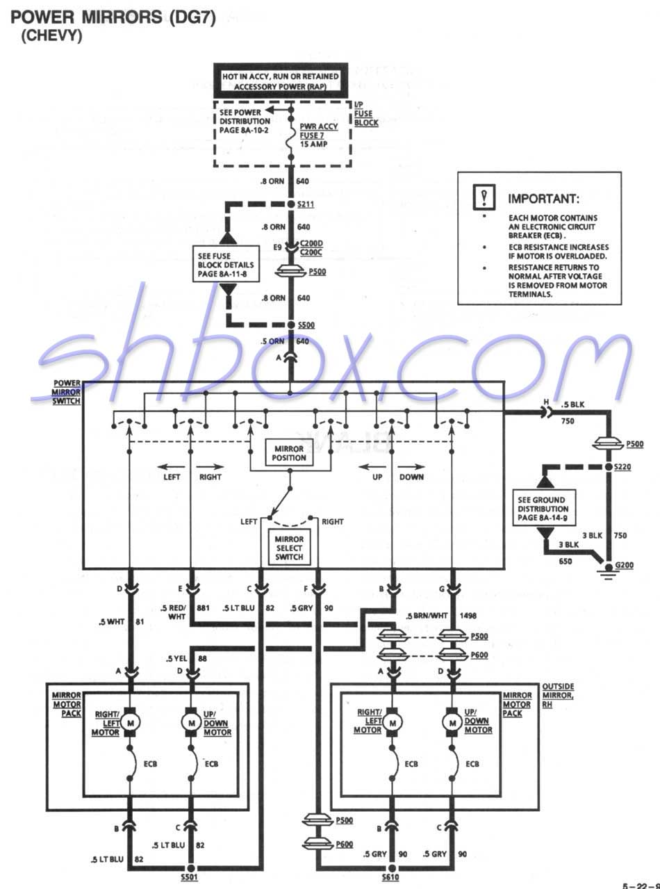
So i saw this thread and i wired my switch up like the one below and well it acts wierd. When i move the toggle to the left side both mirrors move simultanously left and right then when i move the switch to the right both mirrors will only move up and down

Grand Prix: orange = pin: H = Fiero: orange
Grand Prix: white = pin: G = Fiero: white
Grand Prix: green = pin: F = Fiero: green
Grand Prix: green = pin: E = Fiero: green black stripe
Grand Prix: white = pin: D = Fiero: white black stripe
Grand prix: yellow = pin: C = Fiero: yellow
Grand Prix: blue = pin: B = Fiero: blue
Grand prix: black = pin: A = Fiero black

pic of the switch:


here is a schematic of the switch:


IP: Logged
PFF
System Bot
seajai
Member
Posts: 1544
From: Linwood Township, Minnesota
Registered: Feb 2012


Feedback score:    (42)
Leave feedback


Total ratings: 52
Rate this member

Report this Post07-21-2014 07:06 AM Click Here to See the Profile for seajaiSend a Private Message to seajaiEdit/Delete MessageReply w/QuoteDirect Link to This Post
If you look at the wiring of the Grand prix switch, you will see a common wire for both motors. The grey for the right and Lt Blue for the left. The common wire for the Fiero is the Yellow and lt blue. The differences are: 1) the common wire for the Grand Prix is between the up/down and left/right motors for the RIGHT side and the up/down and left/right motors for the LEFT side, whereas on the Fiero the common wire is between the up/down motors for BOTH sides and the left/right motors for BOTH sides. This is why you have both left and right side motors running at the same time. 2) The Grand Prix switch applies power to the common wire opposite of how the Fiero switch does, This will also cause the mirrors to work opposite of the switch position. Here is the Fiero switch diagram:


I had this same issue when I wired in the Toyota mirror switch on my dash swap.

What you need to do is to change the Fiero wiring from direction common to side common. And you will need to switch the wires at the motors so they don't run opposite direction of the switch.

At C303, remove the Yellow wire from cavity "D" and splice it to the LtBlue wire on cavity "A". This operation makes the left side mirror common. At C304, remove the LtBlue wire from cavity "A" and splice it in to the Yellow wire on cavity "D". This operation makes the right side mirror common. Make sure to do this swap on the door side of the connector and not the car side.

NOW this makes the Yellow wire common for the RIGHT and the Lt Blue wire is common for the LEFT side. Attach the Lt blue wire to the Lt Blue wire of the GP switch and the Yellow wire to the Grey wire of the GP switch. This is the hookup for the side selector portion of the switch.

For the motor control portion, attach the White wire of the GP switch to the Fiero White wire and the GP switch Red/White wire to the Fiero Black/White wire for L/R operation. Attach the GP switch Yellow wire to the Fiero Lt Green wire and the GP switch Brown/White wire to the Fiero Lt Green/Black wire for up/dn operation. Attach the GP switch ground to the Fiero Ground wire. This should make the mirrors work correctly. If they run opposite of the direction they should, you will need to remove the mirrors from the doors and swap the position of the Yellow and Lt Green wires and the White and Lt Blue wires at the mirror side wire connector. This will make the motors run in the proper direction.

[This message has been edited by seajai (edited 07-21-2014).]

IP: Logged
mmeyer86gt/gtp
Member
Posts: 3864
From: galt, ca
Registered: Sep 2001


Feedback score:    (161)
Leave feedback


Total ratings: 73
Rate this member

Report this Post07-23-2014 08:41 PM Click Here to See the Profile for mmeyer86gt/gtpSend a Private Message to mmeyer86gt/gtpEdit/Delete MessageReply w/QuoteDirect Link to This Post
Worked perfectly Thank you for the help.
IP: Logged
seajai
Member
Posts: 1544
From: Linwood Township, Minnesota
Registered: Feb 2012


Feedback score:    (42)
Leave feedback


Total ratings: 52
Rate this member

Report this Post07-24-2014 12:13 AM Click Here to See the Profile for seajaiSend a Private Message to seajaiEdit/Delete MessageReply w/QuoteDirect Link to This Post
 
quote
Originally posted by mmeyer86gt/gtp:

Worked perfectly Thank you for the help.


Excellent!

You're welcome
IP: Logged

next newest topic | next oldest topic

All times are ET (US)

Post New Topic  Post A Reply
Hop to:

Contact Us | Back To Main Page

Advertizing on PFF | Fiero Parts Vendors
PFF Merchandise | Fiero Gallery
Real-Time Chat | Fiero Related Auctions on eBay


Copyright (c) 1999, C. Pennock