I have installed the battery upfront as per instructions that came with them. It included a long length of + cable and a short - cable to bolt to body. The 3900 LZ9 that I'm installing has a starter cable on it quite a bit larger than the one in kit. I'm wondering if I should scrap the cable that came with the box and use welding cable of equivalent size? The accessory cable from the engine is just slightly smaller than the cable that came with the box. Do you think the 3900 LZ9 requires that much more amperage?
------------------ Life is just SO much better when you own AND drive a Fiero!
My thought is that GM is cost concerned, so they wouldn't use cables larger than required, plus the length is increased to get from stock location of 3900 to front battery box on Fiero. I also don't like the idea of using the body to complete the circuit. Don't know the gauge of the wires but it is substantially different. Not comfortable running large electrical cables next to fuel tank. May route by coolant tubes. Kinda getting a feel for others that have gone this direction. This covered the fitment of the spare: https://www.fiero.nl/forum/Forum2/HTML/121251.html
[This message has been edited by fierocarparts (edited 06-14-2013).]
2 gauge cable should do it. If you are using the short cable to the frame make sure the engine is grounded at multiple spots. Can't have a good enough ground path.
When I mounted my battery in the front I used 2 extremely long positive battery cables from some junkyard s series BMWs. They appear to be 0 gauge wire and it is long enough. The ones I got were cut on the battery end so I don't know the length of the whole cable. I got the idea from Jalopnik.
Very short version... Wire resistance goes up with distance. Many Starter draws 1.5-1.7Kw 1500w/12.6v(Full charge bat volts)=119amps Before you add all the voltage drops for every connection, wire type/gauge/length, etc.
Welding wire is made to carry high amps at long distance Plus it has Very Tough insulation. Good because any short can/will blow holes in what is in the way... gas tank, coolant pipe, etc. A shorted battery can generate 300-400 amps or more.
A problem using welding wire is the thin wire threads are easy target for water/etc attack. Make sure you waterproof the ends. Coat the end w/ silicon grease then heat shrink.
If you run standard battery cable then use conduit to protect them. Wire maybe good for amp load but insulation is not rated to take road impacts.
If you run a short ground then make sure will never get loose. Ground problems can eat coolant system parts. Coolant is very conductive.
------------------ Dr. Ian Malcolm: Yeah, but your scientists were so preoccupied with whether or not they could, they didn't stop to think if they should. (Jurassic Park)
I use #2 welding cable. I wrap the +ve in some 1/2 inch heater hose slit lengthwise and held in place with cable ties for extra security although it won't really come off. Then I run it along side the a/c hard lines that run by tank and use plenty of cable ties to hold it in place. I usually run just the +ve and taker the -ve to a stud welded to the cross member up front. I also install a cutoff switch on the front cross member in the +ve line so that I can easily disconnect everything as I mount my batteries facing forward so the terminals are a little awkward to get to. I know some people say to run the -ve to the engine as well but I've never had problems. I usually run a #2 cable from the engine to a stud welded to the chassis at the back as well. All I can say is that my setup seems to work fine and I never have any problems.
------------------ Anything I might say is probably worth what you paid for it, so treat it accordingly!
I used #0 welding cable run inside 1" plastic conduit run beside the gas tank for the positive cable (3 layers of insulation there). This runs straight to the starter. I used a smaller #4 welding cable from the alternator to the power block and down to the starter for the charging system.
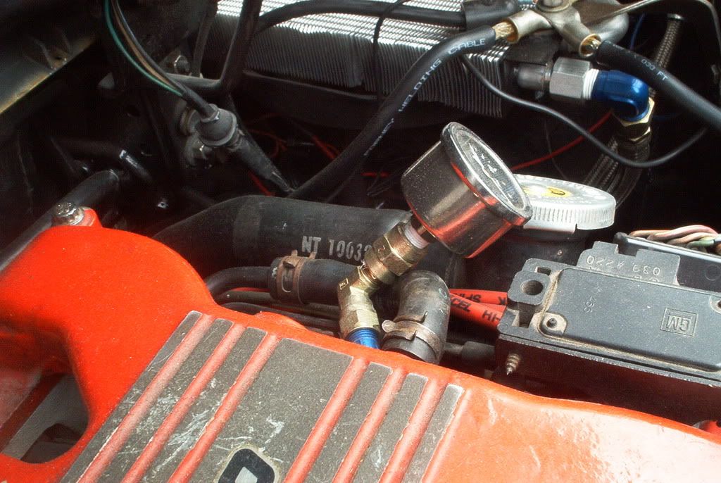
For ground I used #2 welding cable run inside the pax compartment all the way to a common point near the original battery location. You can see where all the grounds came together on my oil cooler at the top of this picture. Engine ground, battery ground, frame ground, ECM ground. Also ran an extra ground from the front cross member to the battery.
When I drag raced in my Nova, I had the battery in the trunk with the positive going to a battery disconnect switch, then up to the starter solenoid. I also had the negative wire grounded to the body at the battery. I had a same size cable from the motor block to body. After my accident, they did not turn off the battery switch, but the cable never shorted out.
Sounds like the majority feels using the body as a conductor for the negative is the way to go. Hadn't thought about running the cable on the inside through the tunnel. I will be losing my throttle cable, so that would be an excellent route out to the engine. Will have to look at entrance from battery box. Y'all have great ideas and methods. I appreciate the input and suggestions.
I ran my cables inside the GT sideskirt / gound effects on the passenger side.
Also, I run a long ground cable also. I have heard of weird problems like the coolant conducting and causing water pump failures. (I take that with a grain of salt, but still....)
[This message has been edited by Jake_2m4 (edited 06-18-2013).]
I mean no disrespect in posting this, just letting you know that you are going to have an issue down the road. If it's a fair weather Fiero it may take years, but it will happen eventually.
You are seriously going to want to attend those connections, water will wick up the strands and ruin the cable, solder or not. It also appears that you melted solder in the connector and stuck the copper in. While that will make a connection that physically holds, if the copper isn't brought up to temp the solder will not wick into the braid of the wire, which creates air gaps for oxidation/corrosion to take hold.
There is a large gauge crimping tool designed to be used on those terminals that literally compresses the metals until they essentially become a solid connection. The gap between the insulation and terminal then needs to be sealed.
As stated before:
quote
Originally posted by theogre: A problem using welding wire is the thin wire threads are easy target for water/etc attack. Make sure you waterproof the ends. Coat the end w/ silicon grease then heat shrink.
[This message has been edited by carbon (edited 06-18-2013).]
Originally posted by Jake_2m4: I ran my cables inside the GT sideskirt / gound effects on the passenger side.
Also, I run a long ground cable also. I have heard of weird problems like the coolant conducting and causing water pump failures. (I take that with a grain of salt, but still....)
Run in rocker panels seem ok... unless hit... Hitting in a minor wreck can short out the battery. Not good. Minor wreck can = a major fire.
"weird problems"? Again not a myth... Coolant is very good becoming a extra ground path when ground wires/connections are weak. Google: coolant electrolysis Normal power is bad enough, when you start the car then pulling any part of starter amps thru coolant causes major problems. Can eat hoses from inside Can also eat heater core, radiator, WP and more. Even the engine gets damage from electrolysis.
Any damage done by electrolysis is nonrecoverable... need to replace the part(s) And a flush to replace the now weak coolant.
Coolant is very good becoming a extra ground path when ground wires/connections are weak. Google: coolant electrolysis Normal power is bad enough, when you start the car then pulling any part of starter amps thru coolant causes major problems. Can eat hoses from inside Can also eat heater core, radiator, WP and more. Even the engine gets damage from electrolysis.
Any damage done by electrolysis is nonrecoverable... need to replace the part(s) And a flush to replace the now weak coolant.
Which is why my primary ground cable runs to the block and and the positive cable runs to the starter.
Originally posted by carbon: I mean no disrespect in posting this, just letting you know that you are going to have an issue down the road. If it's a fair weather Fiero it may take years, but it will happen eventually.
You are seriously going to want to attend those connections, water will wick up the strands and ruin the cable, solder or not. It also appears that you melted solder in the connector and stuck the copper in. While that will make a connection that physically holds, if the copper isn't brought up to temp the solder will not wick into the braid of the wire, which creates air gaps for oxidation/corrosion to take hold.
There is a large gauge crimping tool designed to be used on those terminals that literally compresses the metals until they essentially become a solid connection. The gap between the insulation and terminal then needs to be sealed.
Quoting my why? "Silicone the ends" means silicone the exposed wire part too. A very good coat of silicone oil/grease, like Dielectric grease, will stop or major reduce wicking. The silicone will wick into the wires. Very hard to wash off or displace after too. Maybe a pressure washer...
Many methods doing this has problem. Using the body as return/ground path for starter amps are often = or worse than most.
quote
Originally posted by seajai: LeSabre, Riveria, Bonneville with the battery under the rear seat work perfectly. Used a pair of them on my project.
Like this? https://www.fiero.nl/forum/Forum2/HTML/128284.html Factory made cables should work. Should give anyone else a clue... one wire go to the starter + (picture 3 on right), other bolts to engine (Big terminal, picture 3 on left) and body (small terminals).
I have lots of welding cables so, with this new information and thoughts, sounds like I will run two cables from battery to engine/starter and ground from battery to body near battery and then negative cable on block to various places on the body near engine. Going to run cables through tunnel inside under console. Used to have tools to crimp large lugs onto cables. If not, use old style method. I like the idea of large cables directly to block, didn't like the idea of them exposed to impact near the fuel tank.
I'm in the process of relocating my battery to the front. I've got the battery box installed and I'm about to install the cables. I'm using two positive battery cables from Olds Auroras. One will run from the positive battery terminal to the starter (3800sc). The other will run from the negative battery terminal to a stud on the engine block just above the starter. I will also run a negative from the battery negative terminal to the chassis in the front compartment. I checked the fit of the cables and they are much longer than what is necessary. Anyone used these factory cables before? I'm not sure where to loop the extra cable length. Considering just winding them once around the outside of the battery.
I would shorten the cables. Gunna take pictures of the install. Think I'm going to go beside brake booster vacuum line, through tunnel and out throttle cable opening. nope....
[This message has been edited by fierocarparts (edited 06-21-2013).]
I would shorten the cables. Gunna take pictures of the install. Think I'm going to go beside brake booster vacuum line, through tunnel and out throttle cable opening.
I'd like to see your pics if you are able to post them. I had planned to route underneath by the fuel tank , but may go through the tunnel route.
Tunnel won't work as well as I thought as it will turn the positive cable up towards the exhaust manifold. Looks like a Hybrid install for me. Solid one piece positive cable beside one side of fuel tank. Negative will be "spliced" near fuel tank cross piece. I will run a cable from Battery to that point and another cable from block to that point and bolt them to the body. Run a few grounds from the battery to the body and in the back from the engine to the body. Did find out that the cable that came with the box was #4 welding wire. Not sure what factory used on the Uplander.
Tunnel won't work as well as I thought as it will turn the positive cable up towards the exhaust manifold. Looks like a Hybrid install for me. Solid one piece positive cable beside one side of fuel tank. Negative will be "spliced" near fuel tank cross piece. I will run a cable from Battery to that point and another cable from block to that point and bolt them to the body. Run a few grounds from the battery to the body and in the back from the engine to the body. Did find out that the cable that came with the box was #4 welding wire. Not sure what factory used on the Uplander.
Thanks for the info. I've been out of town and unable to pursue this project, but knowing that the tunnel route is not feasible I'll go back to the fuel tank routing method. I may shorten the cables as suggested, but want to further research how to crimp the cable/connector. In an earlier post to this thread, carbon mentions the existance of a crimping tool that can be used to create a very solid connector. I'm open to other suggestions as I don't know where I might find someone that has one of these tools. Perhaps just crushing the connector/cable in a large vice may achieve a good connection. To use solder I think that it would be necessary to use a torch as the cable would probably absorb all the heat from a soldering iron. One other issue ... I will be using a fairly new side terminal battery and don't want to purchase a top post. The factory cables that I grabbed from a couple of Olds Auroras are equippedd with GM side mount battery terminals so I'd like to use them. For those who have done the front mount battery relocation ... where did you route the cables into the front compartment. I've heard sone bring them up through the spare tire well drain hole (enlarging it), but I plan to keep a spare so that might not work for me. The other two areas I am considering are either the sides, or the front facing side, of the relocated battery box. The factory cables have large rubber firewall grommets on them that would be great for creating a moisture tight seal between, but they are fairly large and would require about a 2" diameter hole.
Seems it works for some to use the interior method. Only problem I found is when it comes out of the rear firewall it goes directly into the exhaust manifold. So I think in the tunnel would be best, if it would clear the exhaust. Instructions show (and it seems to work) taking the cables out the sides of the box and then down near the steering rack. Edit: factory ends aren't soldered. Large lug crimping tool I had, you put lug into slot slip cable in and hit with small sledgehammer.
quote
Originally posted by IFLYR22:
Mine is 0AWG and is run through the interior.
-Dave
[This message has been edited by fierocarparts (edited 06-21-2013).]
Hey guys, dumb question, but I'm trying to buy welding cable and the options are "1 awg, 1/0, 2 awg, and 2/0". What am I looking for? I thought it was as easy as searching "0 gauge welding wire"
Size, from smaller to larger, would be like 4 ga, 2 ga, 1 ga, 1/0 ga, 2/0 ga, 3/0 ga. 4/0ga, etc Think of the 1/0 as Zero gauge, and the larger the number with the 0, the larger the wire . The Bonneville type cables are 2 ga, the same Riviera/Aurora cables are 1/0 Ga. 2ga should be plenty good for what we are doing, but the bigger the better.
------------------ '87 GT in process, including GA / Seville brakes, Poly Suspension, '95 3800 Series 1 SC ( 225 hp ) 4t60e.
When I did the mod, I didn't like the idea of having the big cable hot next to the gas tank, so I used a Ford-style separate starter solenoid and mounted it up front, then ran it from there to the starter- I spiced in another wire to actuate that solenoid and the one on the starter.....I ran a smaller gauge wire back to the block where the battery used to be. I ran the wires in some schedule 40 conduit- You can heat it and bend it so it isn't just straight, but bends up at each end to follow the path of the wires. I can't remember what gaige wire I used- but don't skimp....I'll try to go out and see what gauge I used.
Size, from smaller to larger, would be like 4 ga, 2 ga, 1 ga, 1/0 ga, 2/0 ga, 3/0 ga. 4/0ga, etc Think of the 1/0 as Zero gauge, and the larger the number with the 0, the larger the wire . The Bonneville type cables are 2 ga, the same Riviera/Aurora cables are 1/0 Ga. 2ga should be plenty good for what we are doing, but the bigger the better.
That's what I figured, just wasn't 100% sure. Thanks!


_01.jpg)