Pennock's Fiero Forum
  Technical Discussion & Questions
  H4 to 9005 headlight wiring diagram (for non electricians)

Post New Topic  Post A Reply
Email This Page to Someone! | Printable Version


next newest topic | next oldest topic
H4 to 9005 headlight wiring diagram (for non electricians) by gmctyphoon1992
Started on: 05-14-2016 03:23 PM
Replies: 5 (1383 views)
Last post by: gmctyphoon1992 on 05-19-2016 03:41 PM
gmctyphoon1992
Member
Posts: 693
From: Lighthouse Pt, Florida
Registered: Jun 2010


Feedback score: (3)
Leave feedback

Rate this member

Report this Post05-14-2016 03:23 PM Click Here to See the Profile for gmctyphoon1992Send a Private Message to gmctyphoon1992Edit/Delete MessageReply w/QuoteDirect Link to This Post
I have a diagram that I made from the research I have done on the forum. I understand electrical wiring etc but I am nowhere near an electrician. I am wondering if anyone could tell me if I did this diagram right? If not could someone point me in the right direction or possibly correct my diagram?

Also if I were to add a Diode into this diagram where would it go?

Thankyou for the help.
Conner

This images is larger than 153600 bytes. Click to view.

------------------
1988 Pontiac Fiero Gt (fully optioned, factory leather, 5-speed, CJB T-Tops: Black w/ gray interior and blk wheels)
1992 GMC Typhoon #0203
1971Chevorlet Corvette 454cu/ LS5/ 4-speed/ convertible
1993 BMW 850 Ci 6-speed V-12

IP: Logged
PFF
System Bot
theogre
Member
Posts: 32520
From: USA
Registered: Mar 99


Feedback score: N/A
Leave feedback


Total ratings: 572
Rate this member

Report this Post05-14-2016 04:49 PM Click Here to See the Profile for theogreClick Here to visit theogre's HomePageSend a Private Message to theogreEdit/Delete MessageReply w/QuoteDirect Link to This Post
just a Quick look...
Relays do not need wires to both "H4" outlets. One socket will do.
1 properly installed fusible link at battery end will protect from battery shorted and starting fire. (All fusible link are there for this reason.)
New bulbs get a new ground directly to the frame.

------------------
Dr. Ian Malcolm: Yeah, but your scientists were so preoccupied with whether or not they could, they didn't stop to think if they should.
(Jurassic Park)


The Ogre's Fiero Cave

IP: Logged
gmctyphoon1992
Member
Posts: 693
From: Lighthouse Pt, Florida
Registered: Jun 2010


Feedback score: (3)
Leave feedback

Rate this member

Report this Post05-16-2016 02:33 AM Click Here to See the Profile for gmctyphoon1992Send a Private Message to gmctyphoon1992Edit/Delete MessageReply w/QuoteDirect Link to This Post
 
quote
Originally posted by theogre:

just a Quick look...
Relays do not need wires to both "H4" outlets. One socket will do.
1 properly installed fusible link at battery end will protect from battery shorted and starting fire. (All fusible link are there for this reason.)
New bulbs get a new ground directly to the frame.


Ok so i modified the picture that makes alot of sense all i need is the trigger signal to open and close the relays. As far as the two seperate power sources to the relays I think I will keep that just so if i Blow a fuse on low or high side I will still have headlights no matter what!
Is this picture more correct grounding the actual lamps to the chasis or bucket housing? Im guessing the diode goes from the high signal wire to the low signal wire to keep the lows on when i Put the highs on?

[This message has been edited by gmctyphoon1992 (edited 05-16-2016).]

IP: Logged
theogre
Member
Posts: 32520
From: USA
Registered: Mar 99


Feedback score: N/A
Leave feedback


Total ratings: 572
Rate this member

Report this Post05-16-2016 11:20 AM Click Here to See the Profile for theogreClick Here to visit theogre's HomePageSend a Private Message to theogreEdit/Delete MessageReply w/QuoteDirect Link to This Post
Many systems run 9005 are illegal when both beams are on.
You would need to post more data.
IP: Logged
Synthesis
Member
Posts: 12207
From: Jordan, MN
Registered: Feb 2002


Feedback score:    (19)
Leave feedback


Total ratings: 294
Rate this member

Report this Post05-16-2016 11:39 AM Click Here to See the Profile for SynthesisSend a Private Message to SynthesisEdit/Delete MessageReply w/QuoteDirect Link to This Post
Re: Legality of running with dual headlights and both lights being on. This is legal, as long as no more than four lights in the front of the vehicle are on at any given time when the high beam switch is on.
Many manufacturers with dual beam/dual bulb headlight systems have produced cars with this function that meet all DOT legality requirements.

Retrofits of DOT approved headlamps (such as the Hella modules and the like) also fall within the legal requirements and are acceptable for use on the highway in all states according to Federal DOT requirements, which supercede those of the state.

If you add driving or fog lights to your vehicle in addition to dual beam/bulb fixtures, you can not legally run the driving/fog lights while all four headlights (low AND high beam) are on in many states.

This can easily be modified into an existing wiring diagram to allow the driving/fog lamps to turn off whenever the high beams are on.

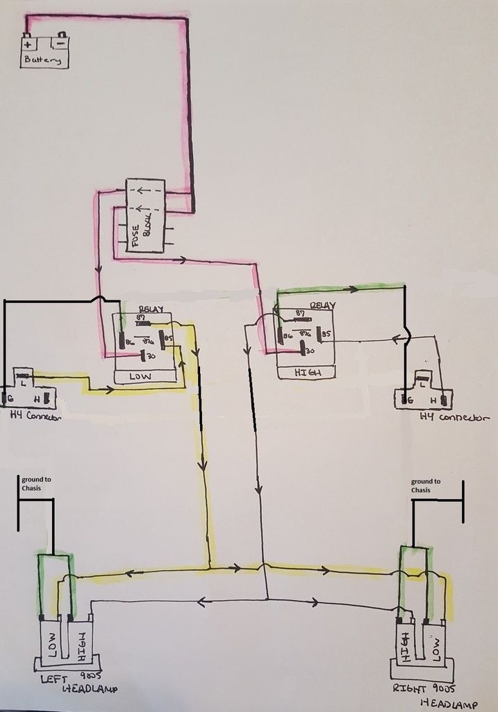
Your comment about a diode running from high to low to keep the low beams on when the highs are engaged is correct. This is exactly what I did and do on harnesses. You can also modify the headlight switch to support this, but a diode sealed into the harness is much cleaner and easier.


Re: the headlight harness information, see this image below. It is what you are looking to do, and works great with all dual beam setups. This is the schematic I created when I was manufacturing headlight harnesses for the 90MM low profile headlight kits.

Note: The information on the Diode was updated in a later post in the thread, as I had listed the wrong part in the image. That thread is located here.

[This message has been edited by Synthesis (edited 05-16-2016).]

IP: Logged
gmctyphoon1992
Member
Posts: 693
From: Lighthouse Pt, Florida
Registered: Jun 2010


Feedback score: (3)
Leave feedback

Rate this member

Report this Post05-19-2016 03:41 PM Click Here to See the Profile for gmctyphoon1992Send a Private Message to gmctyphoon1992Edit/Delete MessageReply w/QuoteDirect Link to This Post
Thankyou again Synthesis and theogre for the help you both have been very helpful Especially the schematic and linked thread!

So its two 14AWG wires from the battery to a fuse block to the low and high side relays. Than I can use 16AWG wire from relays to the 60mm buckets. Do you happen to know the length I would need of these wires?

Also the fuse block has to be within 6 inches of the battery why?

Can I just run 1 power wire fused 6 inches from the battery to the front than split that one wire into three wires to another fuse block for both of the relays and one for the halos or is that not a good idea?

I also need power for my halos and I am wondering how that is possible? Just another fused power wire from the battery to the front I am guessing or is there an easier way? (reminded I am probably going to run the halos off a relay and switch unless there is a better way)

My apologies for the 20 questions I am just trying to make this as easy and simple as possible with the least amount wires everywhere.
IP: Logged

next newest topic | next oldest topic

All times are ET (US)

Post New Topic  Post A Reply
Hop to:

Contact Us | Back To Main Page

Advertizing on PFF | Fiero Parts Vendors
PFF Merchandise | Fiero Gallery
Real-Time Chat | Fiero Related Auctions on eBay


Copyright (c) 1999, C. Pennock