I am trying to add remote door locks and while testing... I must have blown the fuse to the door locks as my door lock buttons are no longer working. I was trying to find the trigger wire for the trunk release at the switch located on the dash. but was not able to make it work.
Can someone point me to the location of the door lock fuse? Or point me in the right direction to troubleshoot?
Any info on a how to install an after market remote installs would be appreciated. I'm only concern with the remote door locks and trunk. Horn, lights, windows and everything else I font really care about.
Here is the instructions for the remote keyless system.
Info was taken from amazon search for 'FICBOX Universal Car Door Lock Vehicle Keyless'
Thank you for the help....
[This message has been edited by str8maxn (edited 12-06-2019).]
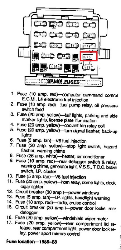
I installed a different system (Avital 2101L) but they don't vary all that much. Your system may have a fuse built in to it; if so check that. The door locks are powered through the Power Accessory circuit breaker, but the Door Lock Switches and Relays are powered through the CTSY/LID fuse. Both are located in the lower right corner of the fuse block (if you're looking at it such that the legends are right-reading).
With my system, after about two weeks of use I had a failure that I traced to the Avital control module. It was under warranty but the thing only cost $31 at the time so I decided to gamble the warranty and see about repairing it (I work in electronics). I found a bad solder joint on a surface-mount transistor array and as soon as I reflowed the solder and re-tested everything was fine. My point is just that this kind of thing happens more often than you might think so it's possible that the problem is the module itself.
A quick test you can run is to disconnect the Opening and Closing Signal wires from the Main Unit. One at a time, momentarily jumper the Opening (white/black wire) or Closing (white wire) to +12V. Just touch the jumper to the wire momentarily - the lock solenoids are not designed to be energized continuously. If the locks respond the problem is the module. If only Opening or only Closing responds, the fuse and Circuit breaker are okay, but the switch or wiring are suspect. If nothing works during this test, re-check the fuse and circuit breaker.
I'll get a look at my FSM and other info from my install and let you know what to jumper to test. In the meantime, check also Fuse #17 - includes the Power Door Lock Relay (but if power trunk release, trunk light, and power mirrors work then this fuse is good).
I'll get a look at my FSM and other info from my install and let you know what to jumper to test. In the meantime, check also Fuse #17 - includes the Power Door Lock Relay (but if power trunk release, trunk light, and power mirrors work then this fuse is good).
Trunk and trunk light are still working so I'll assume that the #17 fuse is still good. Thank you for helping out.
+12 on ORN/BLK wire only is normal. Everything else is switched by the lock/unlock switches and the Door Lock Relay Assembly (the 'module' by the right side kick panel). I'm assuming the wire colors in our photo are a bit washed out. You should have ORN/BLK, LT BLU(2), BLK (2), GRY(2) and TAN(2) - 9 wires total. The Ground connection for this Relay Assembly is the mounting - make sure it securely bolted down.
Since the Door Lock Relay switches both +12 and Ground, some tests with jumpers will require connecting two jumpers at once. All you need to jumper anything for test is a wire a couple of inches long with the ends stripped. If you have the choice, I'd recommend 16 ga. or larger, maybe 3-4" long, ends stripped about 1/4".
Since you said there's power on the ORN/BLK wire, I'll assume you have a meter or a test light. You can find out most things with that. If you connect your meter/test light between the LT BLU and GROUND (Relay case), and press (and hold) the door LOCK switch, you should see battery voltage. If you connect your meter/test light between the BLK and GROUND, and press (and hold) the door UNLOCK switch, you should see battery voltage. Do this with both switches. (If only one works, the switch that doesn't is bad, or its wiring is) If these tests work, you're good up to the Relay Assembly. If you connect your meter/test light between the GRY and GROUND (Relay case), and press the door LOCK switch, you should see battery voltage. If you connect your meter/test light between the TAN and GROUND (Relay case), and press the door UNLOCK switch, you should see battery voltage. If these tests work, the Door Lock Relay Assembly is good. (There are ways to substitute this since it is not available new AFAIK. Used ones may be available.
The above tests will probably find the problem.
If you want to test the Door Locks themselves, you can jumper the GRY to ORN/BLK and TAN to GROUND, and the doors should LOCK. If you jumper the TAN to ORN/BLK, and GRY to GROUND, the doors should UNLOCK. IF YOU DO THIS, connect the last jumper only momentarily touching it to make contact and expect it to arc. It's not particularly dangerous, but you're shorting a significant current (that's why there's a relay between the switches and the door actuators). In fact, if the Relay tests good, You're probably better off plugging everything back in and testing that way. Everything after the lock/unlock switches is wired in parallel and the odds that both sides died at once, or that the wiring for both sides failed at once, are quite small.
OldGuyInaGT- Thank you very much for the help... Turns out the first paragraph of your troubleshoot had the solution.... All I had to do was ground the Stock Relay.
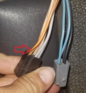
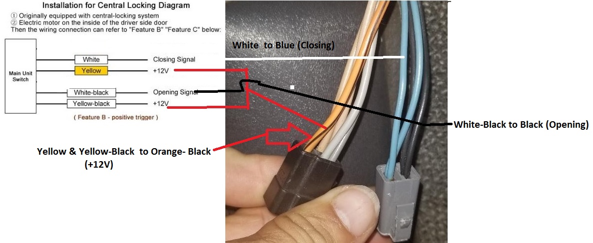
I have the lock and unlock figured out and working. I'd like to share this pic and hope it helps people in the future.
This is what my wiring looks like:
All I need now is the trunk release. If you or anyone else can tell me where the wire is located and what wire to use for the trunk release that would complete my mode. ( I have a 1986 GT)
The after market module has a - Negative trigger .
Do I need to add a relay?
[This message has been edited by str8maxn (edited 12-15-2019).]
My system is the same - the channel for the trunk release is switched negative (negative trigger). I added a relay. The best location I found was under the dash near the steering column. I wired the relay contacts between an unused BAT terminal on the fuse block and the wire from the trunk switch to the trunk release relay (GRY/BLK wire) Coil went to same BAT terminal via a jumper near the relay socket (I always use sockets when adding a relay) and the negative trigger lead of the module . You can wire the relay contacts from BAT directly to the trunk release solenoid (BLK/WHT wire) but this bypasses the trunk release relay. I like NOT bypassing this because then the key fob will only open the deck lid when the transmission is in Park or Neutral (auto trans) or when the parking brake is applied (manual trans), like the existing switch.