Pennock's Fiero Forum
  Technical Discussion & Questions
  Improving V6 upper manifold flow

Post New Topic  Post A Reply
Email This Page to Someone! | Printable Version


next newest topic | next oldest topic
Improving V6 upper manifold flow by cvxjet
Started on: 05-27-2020 06:26 PM
Replies: 14 (628 views)
Last post by: fieroguru on 06-05-2020 07:22 AM
cvxjet
Member
Posts: 3761
From: ca, usa
Registered: May 2010


Feedback score: (1)
Leave feedback

Rate this member

Report this Post05-27-2020 06:26 PM Click Here to See the Profile for cvxjetSend a Private Message to cvxjetEdit/Delete MessageReply w/QuoteDirect Link to This Post
Here is my....adventure...If you have any questions feel free!

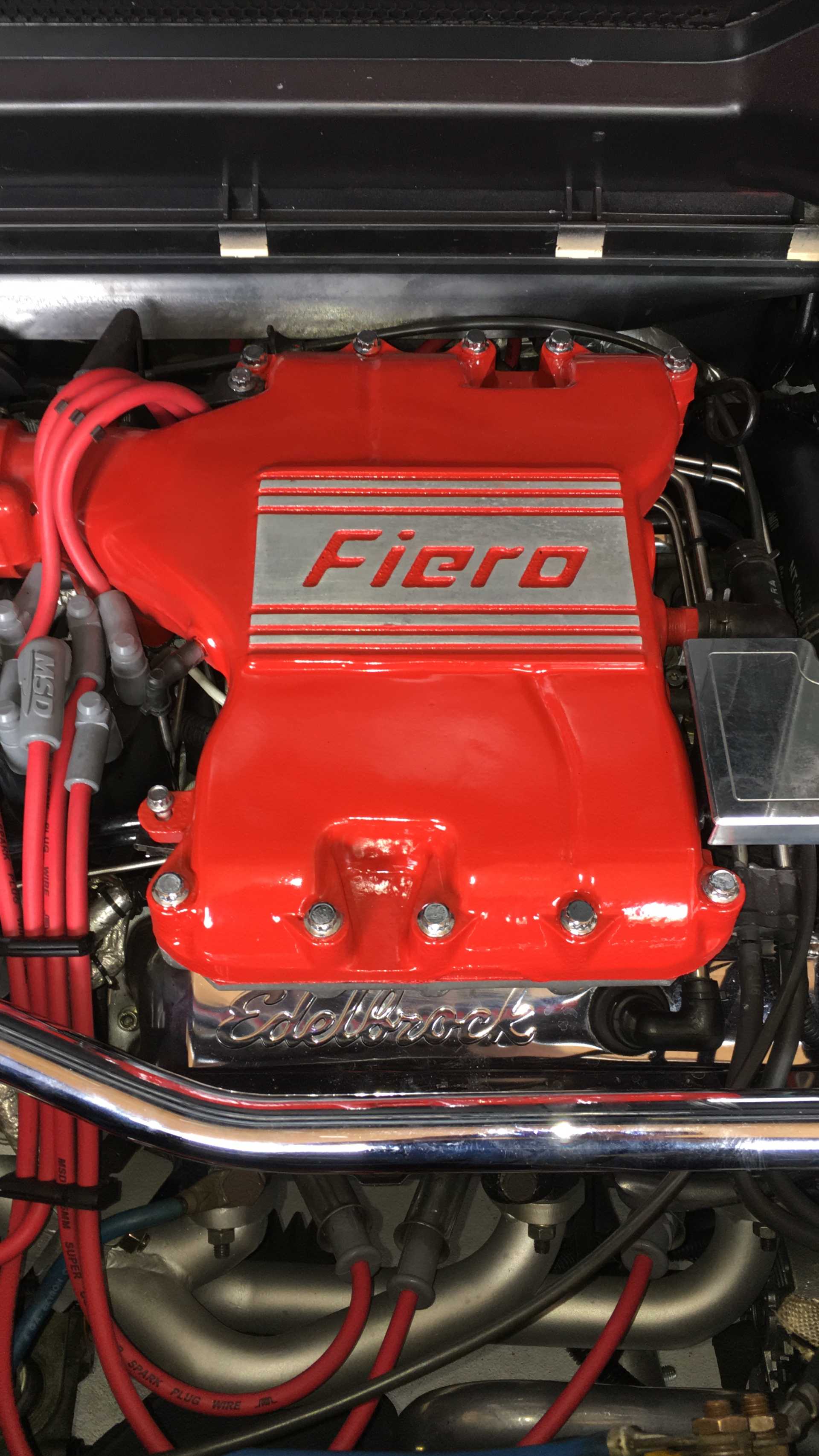
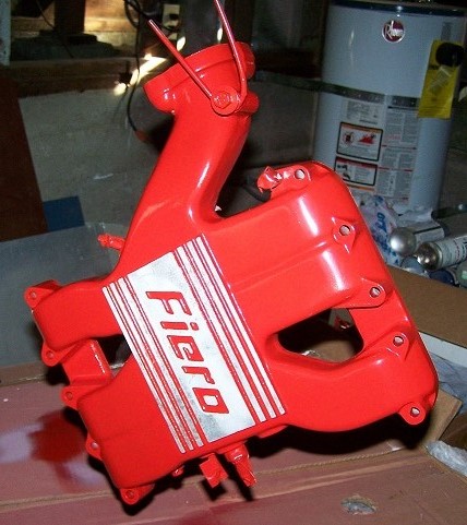
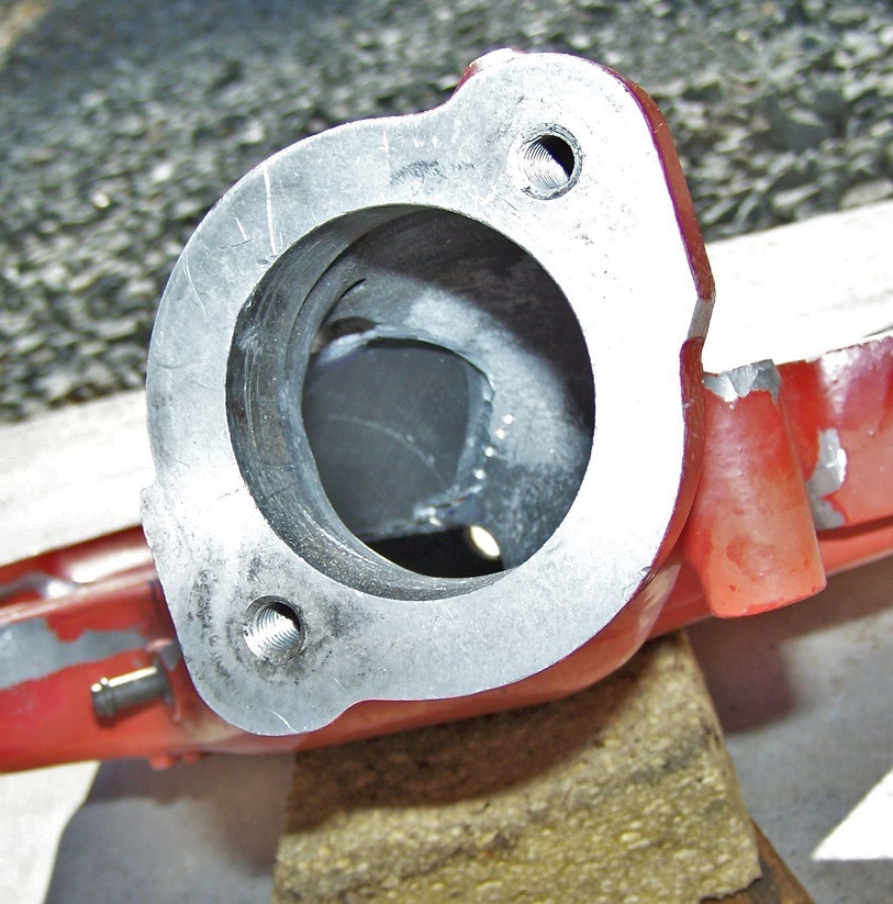
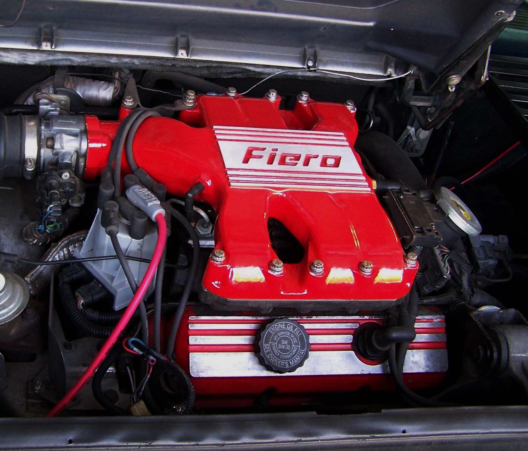
I have a 1985 SE V6 that I have owned since new; Over the years I have done a number of mods- 88 rear subframe and brakes all around, Getrag 5 speed trans, moved the battery up front, 86-88 GT rear bodywork, and 3.4 L F-body long block. The 3.4 breathing thru the original 2.8 induction system doesn't pull beyond 4600 rpm....I found out that the "pinch-point" in the 2.8 manifold is right where the main passage blends into the plenum....A guy actually did some flow bench testing and proved that between modding the manifold and opening up the Throttle-body, it was the manifold that made the big difference. Also, I never did like the 1985-86 "Decal" manifolds- The later ones have the "Fiero" name cast in.

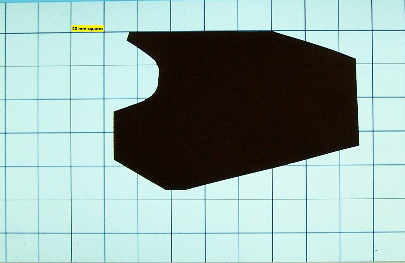
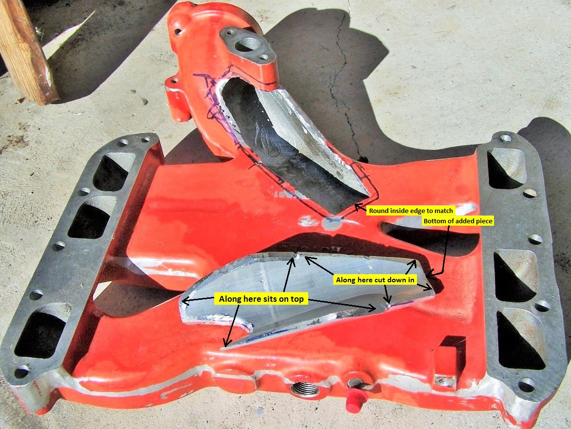
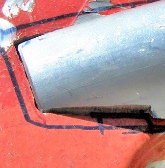
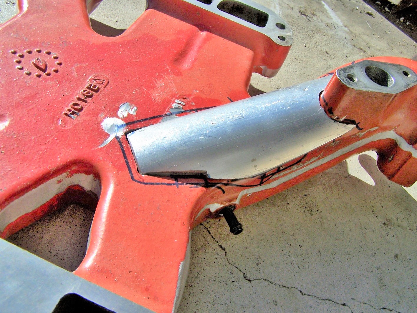
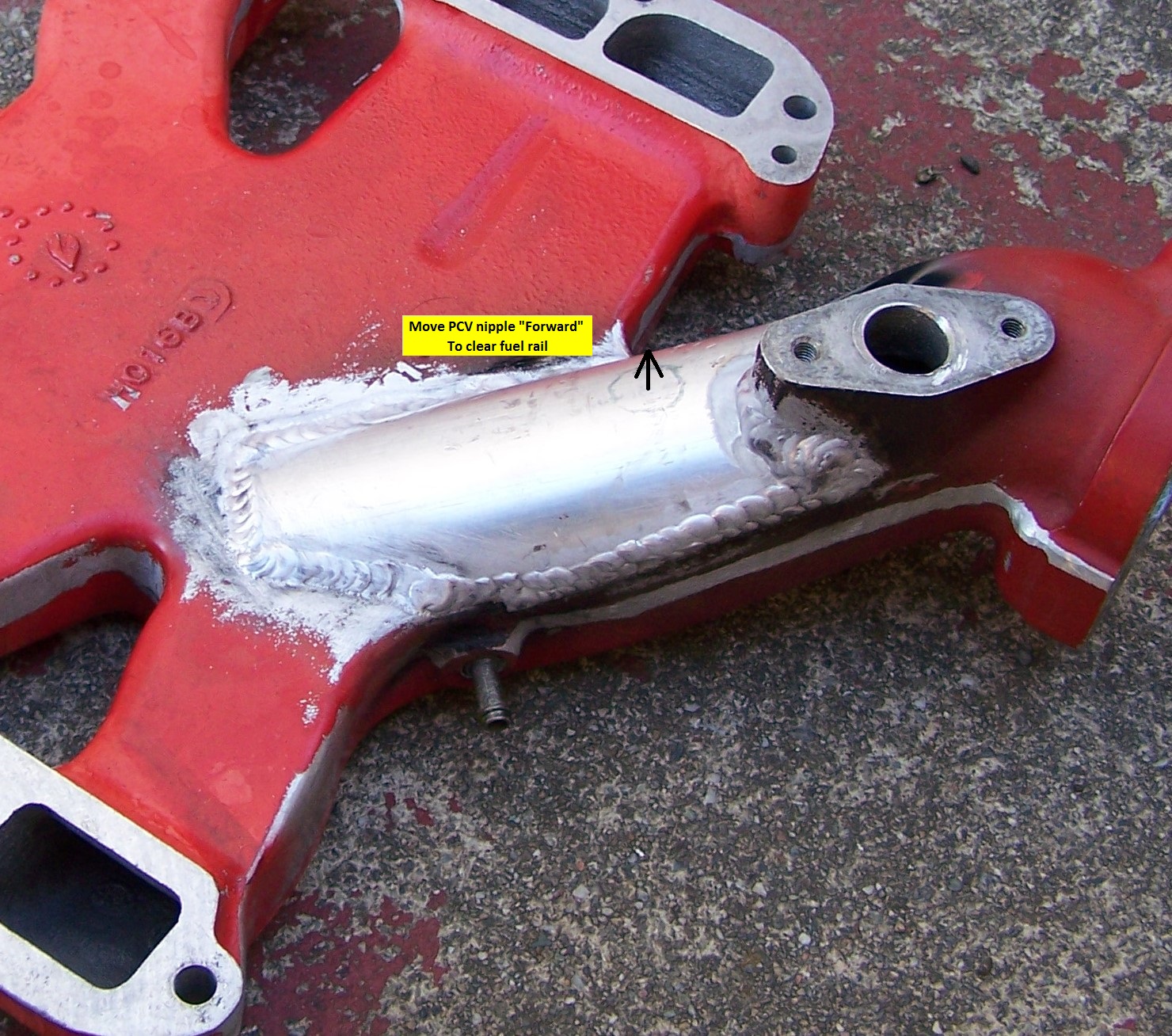
I found a 87-88 upper manifold in the junkyard, and then bought some 1/4" thick aluminum tubing 2" ID and started slowly trimming it and the manifold to blend it in to open that point....It was very time consuming but since I retired I had plenty of time. A friend who is a great welder welded it up for free. I also took some time smoothing the casting lines and removed the cast on mounting for the coolant lines to the TB. I also want to state that you should save the PCV nipple after cutting away the section of manifold where it mounts- any screw-in nipple will stick down farther and interfere with the lower manifold and or fuel rail- In fact, I actually moved the mounting point forward to make it clear the rail. Drilled the hole so a "Tight" fit and hammered it home with some RTV to make positive seal.

Now I needed to paint it- prepping entailed stripping the rest of the paint off the manifold, so I ground and sanded it, then ground and sanded some more- If I was to do it again, I would use some form of chemical stripper (It took me a month of work) I also noticed some pits in the fins and "Fiero" part of the manifold- but figured that once I was done painting I would just sand that area down eliminating the pits.......

I selected Duplicolor engine enamel with ceramic in Chrysler red along with their Primer w/ Ceramic. I didn't want to get any paint on the screw threads for the throttle mounting or the MAP sensor, so I ran some spare screws into them to protect them. The one at the farthest "Left" of the manifold was one with a large washer so I could hang the manifold (Securely) from a hook for painting.

I taped off the openings and wrapped the nipples with tape also- I also taped off the fins and Fiero area so I wouldn't have to sand a bunch to remove paint......Wiped it down with Duplicolor Grease and wax remover, then started painting it. I had read the directions carefully (Yes- I turned in my Man-Card!) and had written a time line for priming and painting; Lite prime, 10 minutes, lite prime, 10 minutes, medium prime, then 45 minutes, lite paint, 10 minutes, lite paint, 10 minutes, medium paint, 10 minutes, medium paint, then 3 hours...at which point I pulled off the tape (Carefully) and then stuck it in my dryer at medium heat for an hour (My dryer came with a "Shoe rack" and I have used it before drying cleaned parts or painted parts)

Two days later I started sanding the fins and "Fiero" area.......Started with 60 grit, then after a few days changed to 180 grit, using a wood sanding block and going slow- so as not to scratch the new paint...and then I realized that those dang pits were deeper than I had originally thought- one was definitely at least 1/16" deep! The sad thing is, if I had been smart (Haha!) I would have had my welder friend just tap those and filled them....now I am afraid it will cook the paint off- Luckily my car is no "Show car" so it's not that important- but a word to the wise- get everything done BEFORE painting!

Testing; Before installing the new ported manifold, I tested the car by going out to the Dublin grade on 580.....In Dublin I headed up hill (Going west) with a 5-8 mph head wind, and also with a 150 lb passenger. In 4th I was able to get the car up to 4500 rpm but then it basically stopped accelerating.

After installing the modified manifold, I took the car out (With that same passenger) to Dublin and headed up the Dublin grade again....It seemed to more rapidly accelerate up to 4500, and then continued up past 4700 and was still pulling. Not a huge change but noticeable.

Some others have shortened the individual runners which has the effect of moving the resonance up in the RPM range (moving the HP and Torque peaks up)...sounds good in theory- But the problem is you are then at a disadvantage because of your gear ratio; You actually want the Power band to be as low as possible in the RPM range. When I swapped in the 3.4, it added (Approx') 20 HP....But my 0-60 dropped from 7.5 to 6.5 seconds- that would require a bigger HP increase- but what made the difference was that the power band was at approx' 1000 rpm lower- which would be like changing the differential gear to a better (Higher numerically) ratio.

I suspect that a minor mod to shorten the runners along with this upper plenum mod would net the best results....

Addendum; I could have done a better job of blending inside after the welding was done, but truthfully, I was tired of messing with it. The area around the EGR mounting is really difficult to blend well.


[This message has been edited by cvxjet (edited 05-27-2020).]

IP: Logged
PFF
System Bot
Patrick
Member
Posts: 37447
From: Vancouver, British Columbia, Canada
Registered: Apr 99


Feedback score: (1)
Leave feedback


Total ratings: 464
Rate this member

Report this Post05-27-2020 07:26 PM Click Here to See the Profile for PatrickSend a Private Message to PatrickEdit/Delete MessageReply w/QuoteDirect Link to This Post
 
quote
Originally posted by cvxjet:

I could have done a better job of blending inside after the welding was done, but truthfully, I was tired of messing with it.


Yes, whenever I see these modified upper intakes, I can't help but wonder how smooth the joins are on the inside. All kinds of funky, possibly disruptive, air flow patterns may result from the relatively rough seams. However, unless the "neck" could be detached/unbolted from the upper intake to allow access, I don't know how the inside joins could be better blended.

Nice job though, looks good.
IP: Logged
cvxjet
Member
Posts: 3761
From: ca, usa
Registered: May 2010


Feedback score: (1)
Leave feedback

Rate this member

Report this Post05-27-2020 08:45 PM Click Here to See the Profile for cvxjetSend a Private Message to cvxjetEdit/Delete MessageReply w/QuoteDirect Link to This Post
Luckily, the fuel is added down stream so it's not as bad as say a carbed or TBI system. I had a rotary file mounted on an extension, but it was really hard to use and see what I was doing- maybe in a few months I'll take it off and do some more grinding.

I think the manifold looks 100% better simply because I ground off the casting lines and that boss for mounting the TB water lines...cleaned up the manifold a lot....

IP: Logged
Notorio
Member
Posts: 2979
From: Temecula, CA
Registered: Oct 2003


Feedback score: (3)
Leave feedback

Rate this member

Report this Post05-27-2020 11:55 PM Click Here to See the Profile for NotorioSend a Private Message to NotorioEdit/Delete MessageReply w/QuoteDirect Link to This Post
Well done sir! Very nice write up and excellent looking finish! (In fact the intake looks so good you might consider repainting the valve covers to match ... )

IP: Logged
cvxjet
Member
Posts: 3761
From: ca, usa
Registered: May 2010


Feedback score: (1)
Leave feedback

Rate this member

Report this Post05-28-2020 12:06 PM Click Here to See the Profile for cvxjetSend a Private Message to cvxjetEdit/Delete MessageReply w/QuoteDirect Link to This Post
Thanks Notorio.....I know that those valve covers need painting bad- If you look carefully, you can see that the paint has actually peeled off the inner side.....But I have to pull more stuff to get to them, so I will when I have time.
IP: Logged
Habanera Hal
Member
Posts: 330
From: Ocala, FL
Registered: Apr 2012


Feedback score: N/A
Leave feedback

Rate this member

Report this Post05-28-2020 03:59 PM Click Here to See the Profile for Habanera HalSend a Private Message to Habanera HalEdit/Delete MessageReply w/QuoteDirect Link to This Post
Nice job and write up!

Just a thought...has anyone attempted to 3-D print a better flowing manifold? Any reason it would have to be aluminum and not plastic? It could have a detachable/changeable throttle body mount, be segmented for better porting access, etc. Any thoughts?
IP: Logged
cvxjet
Member
Posts: 3761
From: ca, usa
Registered: May 2010


Feedback score: (1)
Leave feedback

Rate this member

Report this Post05-28-2020 09:32 PM Click Here to See the Profile for cvxjetSend a Private Message to cvxjetEdit/Delete MessageReply w/QuoteDirect Link to This Post
My crazy/Weird idea would be to have a manifold made that had improved air flow- and with a lower piece that fit to the aluminum splayed-valve heads, and yet looked Fiero stockish (the top had the same basic shape with "Fiero" on it)

From what I have read, the plastics that are available for 3D printing are not really conducive to the intake manifold environment....
IP: Logged
jjd2296
Member
Posts: 1438
From: toronto ON
Registered: Jan 2016


Feedback score:    (8)
Leave feedback

Rate this member

Report this Post05-29-2020 06:53 AM Click Here to See the Profile for jjd2296Send a Private Message to jjd2296Edit/Delete MessageReply w/QuoteDirect Link to This Post
Just do what I did. Cut the bottom off fill in the gaps remover the internal runners and widen the neck. Best improvement on stock plenum

[This message has been edited by jjd2296 (edited 05-29-2020).]

IP: Logged
sourmash
Member
Posts: 4558
From:
Registered: Jul 2016


Feedback score: N/A
Leave feedback


Total ratings: 50
User Banned

Report this Post05-29-2020 09:24 AM Click Here to See the Profile for sourmashSend a Private Message to sourmashEdit/Delete MessageReply w/QuoteDirect Link to This Post
What kind of TIG welder did you use to do that, and what material?
IP: Logged
jjd2296
Member
Posts: 1438
From: toronto ON
Registered: Jan 2016


Feedback score:    (8)
Leave feedback

Rate this member

Report this Post05-29-2020 10:02 AM Click Here to See the Profile for jjd2296Send a Private Message to jjd2296Edit/Delete MessageReply w/QuoteDirect Link to This Post
I did it do the fab work I had a friend do it he works with aluminum all aluminum welds from inside then smoothed before putting the bottom on. Top I had to finish off with aluminum filler sand and paint
IP: Logged
cvxjet
Member
Posts: 3761
From: ca, usa
Registered: May 2010


Feedback score: (1)
Leave feedback

Rate this member

Report this Post06-01-2020 12:11 PM Click Here to See the Profile for cvxjetSend a Private Message to cvxjetEdit/Delete MessageReply w/QuoteDirect Link to This Post
Some people have asked for a pattern....Can't go out and buy graph paper at the moment, so I was able to bring some up on my laptop, then take a pic....the grid squares are 20 mm each.....Not sure how to adjust the pic/printing size so they are right on a printed sheet.......(Anyone know how?)

[This message has been edited by cvxjet (edited 06-01-2020).]

IP: Logged
PFF
System Bot
bootdsc
Member
Posts: 11
From: AZ
Registered: May 2020


Feedback score: N/A
Leave feedback

Rate this member

Report this Post06-04-2020 08:07 PM Click Here to See the Profile for bootdscSend a Private Message to bootdscEdit/Delete MessageReply w/QuoteDirect Link to This Post
So did you dyno test before and after the mod or have some other way of knowing this made any difference?
IP: Logged
cvxjet
Member
Posts: 3761
From: ca, usa
Registered: May 2010


Feedback score: (1)
Leave feedback

Rate this member

Report this Post06-04-2020 09:20 PM Click Here to See the Profile for cvxjetSend a Private Message to cvxjetEdit/Delete MessageReply w/QuoteDirect Link to This Post
 
quote
Originally posted by cvxjet:
Testing; Before installing the new ported manifold, I tested the car by going out to the Dublin grade on 580.....In Dublin I headed up hill (Going west) with a 5-8 mph head wind, and also with a 150 lb passenger. In 4th I was able to get the car up to 4500 rpm but then it basically stopped accelerating.

After installing the modified manifold, I took the car out (With that same passenger) to Dublin and headed up the Dublin grade again....It seemed to more rapidly accelerate up to 4500, and then continued up past 4700 and was still pulling. Not a huge change but noticeable.


This was the only testing so no....No dyno.....
IP: Logged
Notorio
Member
Posts: 2979
From: Temecula, CA
Registered: Oct 2003


Feedback score: (3)
Leave feedback

Rate this member

Report this Post06-04-2020 11:32 PM Click Here to See the Profile for NotorioSend a Private Message to NotorioEdit/Delete MessageReply w/QuoteDirect Link to This Post
Thanks for putting out the template!! I'm saving it into my Fiero 'to do' folder, so I don't have to find it again later
IP: Logged
fieroguru
Member
Posts: 12251
From: Champaign, IL
Registered: Aug 2003


Feedback score:    (45)
Leave feedback


Total ratings: 259
Rate this member

Report this Post06-05-2020 07:22 AM Click Here to See the Profile for fieroguruSend a Private Message to fieroguruEdit/Delete MessageReply w/QuoteDirect Link to This Post
 
quote
Originally posted by bootdsc:

So did you dyno test before and after the mod or have some other way of knowing this made any difference?


There has been a lot of flow bench and dyno work in the past to identify the issues with the stock fiero intake. Here are a couple of good threads (there are others as well).
https://www.fiero.nl/forum/Forum2/HTML/118417.html
https://www.fiero.nl/forum/A...130314-1-082335.html
IP: Logged

next newest topic | next oldest topic

All times are ET (US)

Post New Topic  Post A Reply
Hop to:

Contact Us | Back To Main Page

Advertizing on PFF | Fiero Parts Vendors
PFF Merchandise | Fiero Gallery
Real-Time Chat | Fiero Related Auctions on eBay


Copyright (c) 1999, C. Pennock