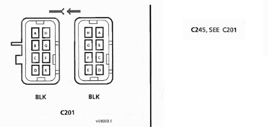
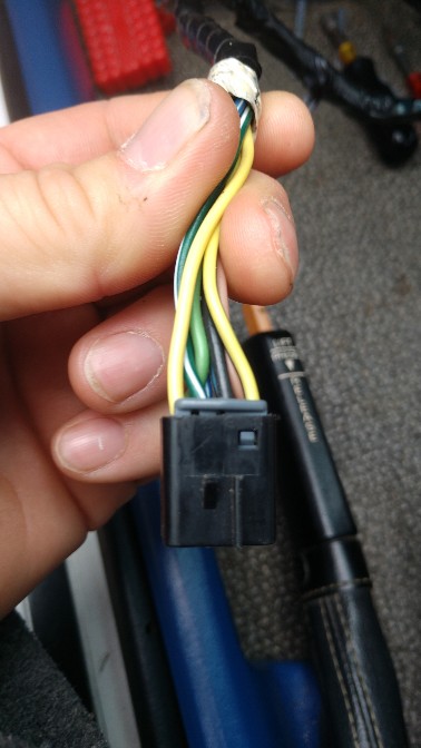
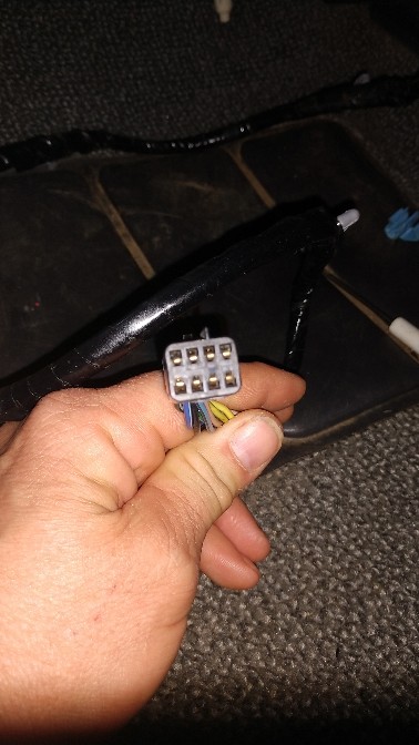
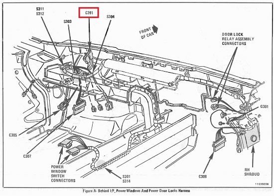
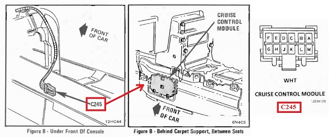
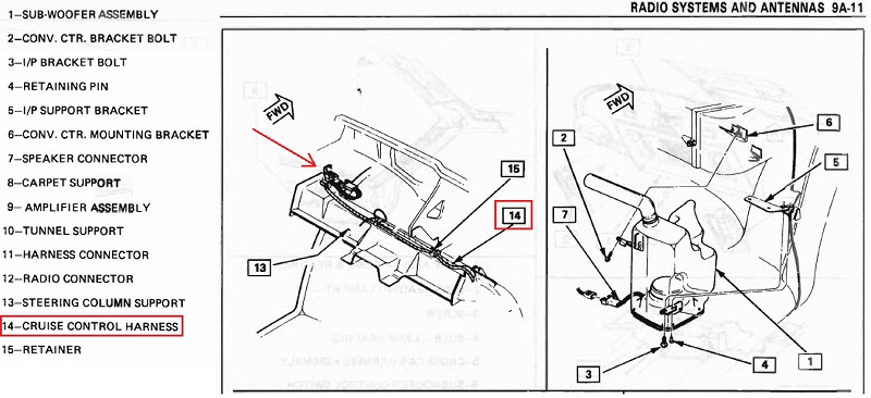
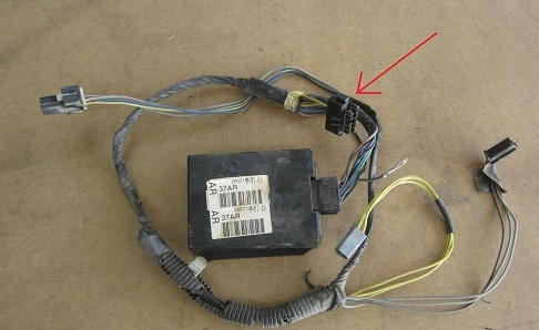
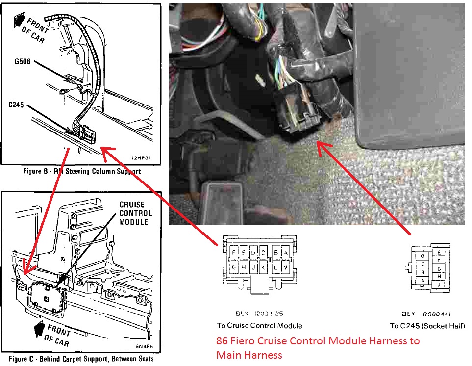
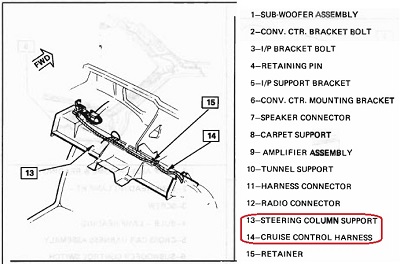
Finally got a chance to disassemble my interior pieces (for the 50th time) to look for the hidden connector that connects the other end of C245 from the 87 cruise control electronics module to the 'spinal cord' harness. Since I was going to be installing
-->Matt's 3D printed skeleton<-- since mine was beyond repair after many band-aid fixes, for the first time I was able to get a look at the area under the big black rectangular support part of the old skeleton in front of the ECM to see what lurks beneath.
And voilà: I Found it!The person who sold me the CCE Module with harness was great to keep those retainers clips in perfect condition.
Cruise Control Electronic Module Connector Location: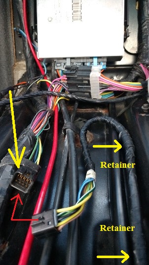
Since I had the entire dash out also, I routed the switches/stalk/cruise-light-mod (see below) the proper route.
 Thanks to Fierofreak00 for this write upAdding CRUISE Light:
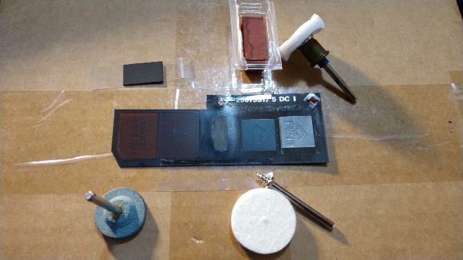
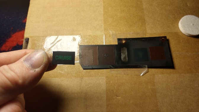
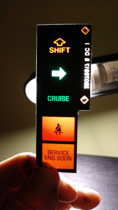
Instead of cutting the original instrument cluster indicator light filter, I carefully
hand ground away the coating with a Dremel wheel. Then lightly polished it. If I had to do it again, I might've used a tad of brake fluid. The extra layer of plastic does slightly weaken the light passing through, but to me looks more stock. I also applied very-very small amounts of black RTV with a tooth pick around the small
CRUISE cut-out when I went to put it on the original light filter and let it sit with tape/tooth pick across it and clamp for good adhesion. Plus the Buick Regal donor that I got the
CRUISE filter from had a slight curve to it due to age and sitting in the junk yard heat. Had to redo it 3 times (always happens to me! Third times charm) to get it right and aligned. Also
FINALLY took care of the pegging temp gauge fix I've been waiting to do at the same time while I was in the instrument cluster.
Got a rear wiring harness with the cruise connections off eBay. The description said no cuts or splices..., my luck ain't that great. Was missing the driver-side rear side marker socket, and looked like someone already spliced and repaired with excessive extra wire. Not to mention someone stopped short of cutting the connector for the Servo/Solenoid/Trunk light. I redid the entire harness. All new electrical tape. New split loom. New routing clips and retainers. Solder and heat shrink. Cherry.
Rear Wiring Harness: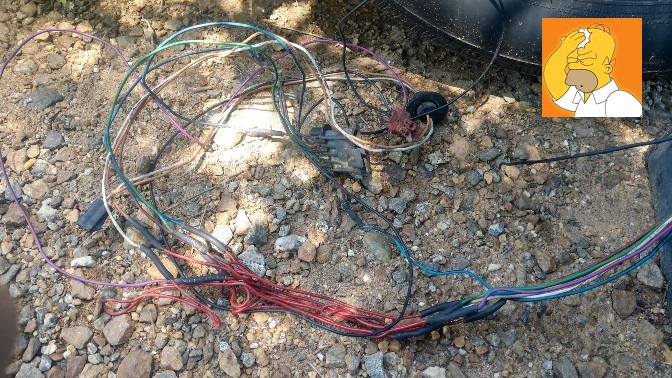
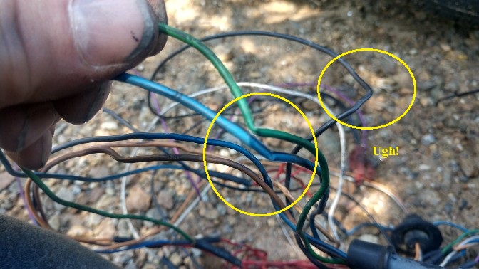
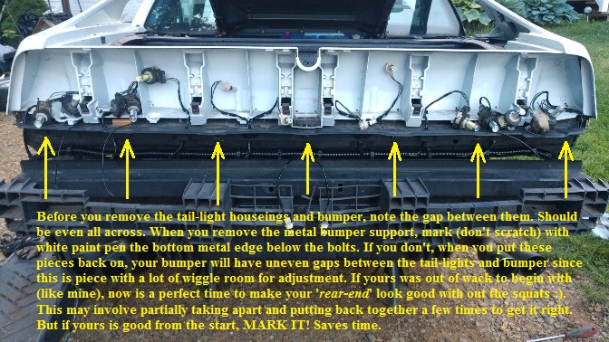 Installing the engine bay Servo/Solenoid/Bracket/Throttle-cable parts:
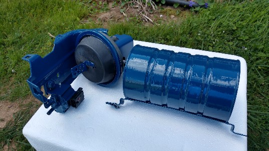
All components are used pulls, except the Tank is from TFS. With a nice coating of POR-15 and some blue. It's also advised to
test the vacuum dump solenoid before installing. Apply 12 volts to it at the connection point using any 12 volt power source. You should hear a
>click<. Remove the 12 volts. Using a clean piece of tubing, attach to inlet and blow into it. Air should flow freely through it out the back port with the filter clip attached. Mine was clogged. By sticking a piece of small gauge solid copper wire along with some PB blaster in the inlet/outlet ports and wiggling around for a while. LUCKILY, I got something loose and blew out a couple small pieces of rust. Makes sense since when I got the setup, the inlet port was rusted a bit inside. Apply 12 volts again and blow through it. Air flow should stop. Using a multi-meter, check for ohms on the 2 pins. Should get around 25 OHMS. There may be a replacement for this solenoid if yours is shot: ACDelco 214-357. Haven't bought it, so I'm not sure if it's a normally open valve. And may have to plug one hole and remove the built-in mount screw.
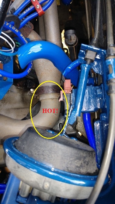
Installing the Vacuum Reservoir Tank (The Coffee Can):Another set back. Ugh. Because I have non-stock exhaust headers and cross-over pipe, the actual mount points for the tank puts the bottom of the tank 1/8" away from sitting on the exhaust system. I've got the
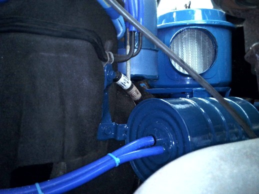
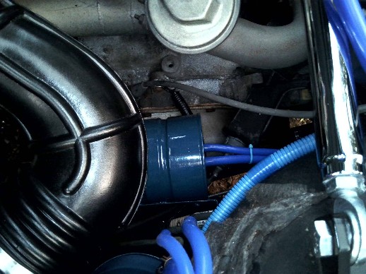
WCF 2.8 "Shorty" headers. So I had to mount the tank elsewhere. Luckily there's plenty of space below the vapor canister and air-filter. Using an existing mounting hole, adding one to the bottom leg of the air filter mount and then fabricate my own extender bracket, the project can proceed.
Original Tank Mounts.
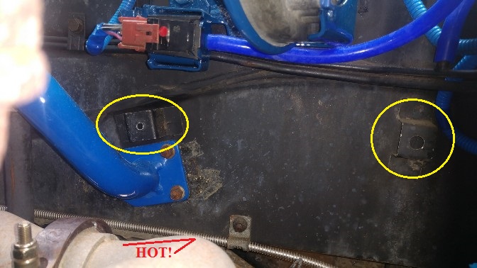
Too close!
New location with bracket.
4" of clearance from cross-over pipe.
 Question, I know I need to make some heat shields. Diaphragm feels like it's gonna melt, and Tank still gets toasty enough where I think it might melt the plastic valve piece. Should I make 2 shields covering them? Or should I just take the original 2.8 cross-over heat shield and modify just that and be safe? Suggestions appreciated.Installing Pedal Switches:
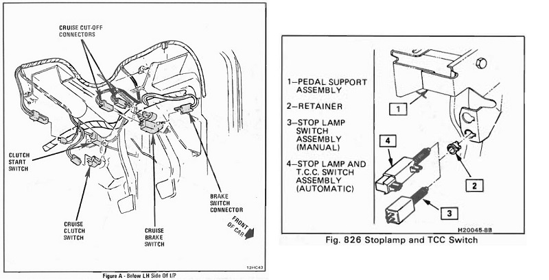
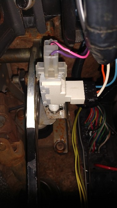
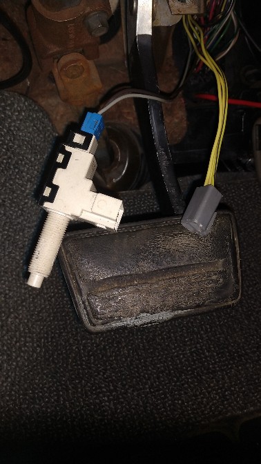
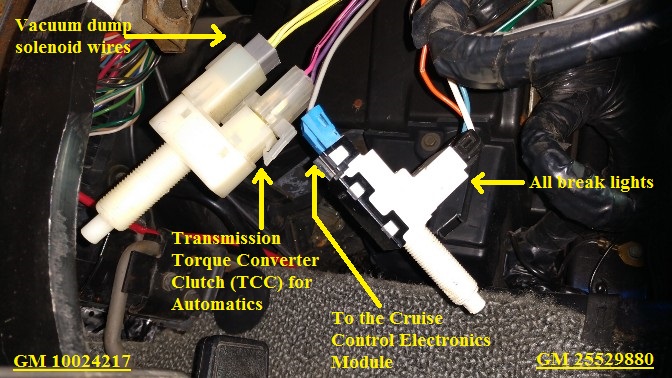
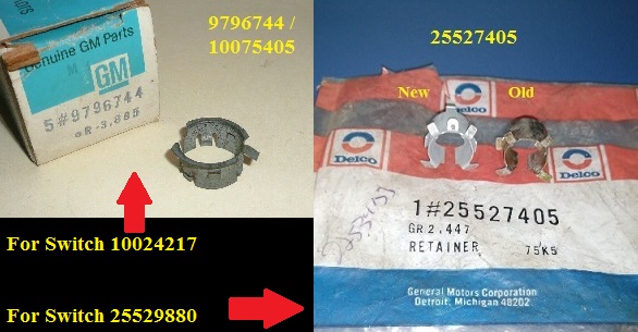
Old brake pedal switch for 87 automatic with third brake light (GM 25529881) needs to be replaced with GM 25529880. I also needed a new retainer for it GM 25527405 since I butchered my old one. The other brake pedal switch needed for the cruise control is GM 10024217. Also needed the retainer for it, GM 9796744 / 10075405.
 First test drive:
Ignition key to 'ON', I hear the
>click< (engaged) from the vacuum dump solenoid. Press break peddle,
>click< (dis-engage), release brake
>click< (engaged). That's good. Got my gal up to 45 MPH, switched the Stalk to 'ON', then 'Set'.
CRUISE light came on my dash, but was not holding speed at all. Tapped brake,
CRUISE light went off. Those circuits are good. OK, while on this test drive I though I'd test to see if the CCE module was communicating with the ECM and speed sensor. Going 20 MPH, tried to set cruise. No go, no CRUISE light. That's good, since it's only supposed to operate at 25 MPH+. Head home for more trouble shooting. Using this write up from the forum,
Cruise Control Testing, along with the 87FSM, I was able to narrow it down to the Servo. Removed the Servo.
Let's take a look inside and see if it can be salvaged. Don't want to spend $50-$120 on a re-manufactured one. I wasn't thinking when I was talking it apart and putting back together to take pictures, I cleaned and painted internal metal parts as I was repairing.
The Servo: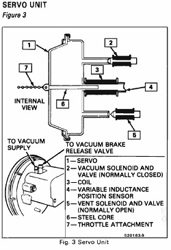
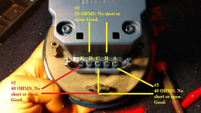
After continuity test described in the picture, using your 12 volt power source, hook up A and C. You should hear a
>click<. Now hook up C and E. You should hear a
>click<.
In my case, A and C the solenoid didn't engage (no
>click<). Off comes the Servo cover.
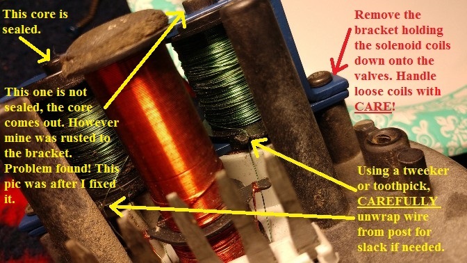
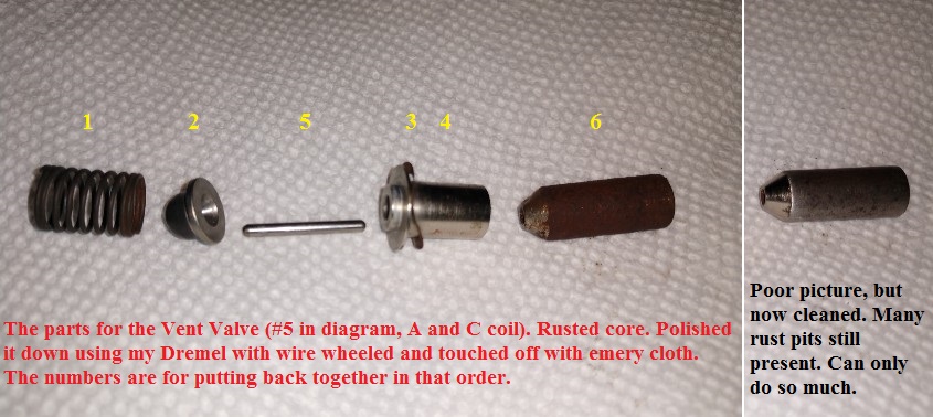 Here's what I got on my plate. Ha!
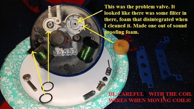
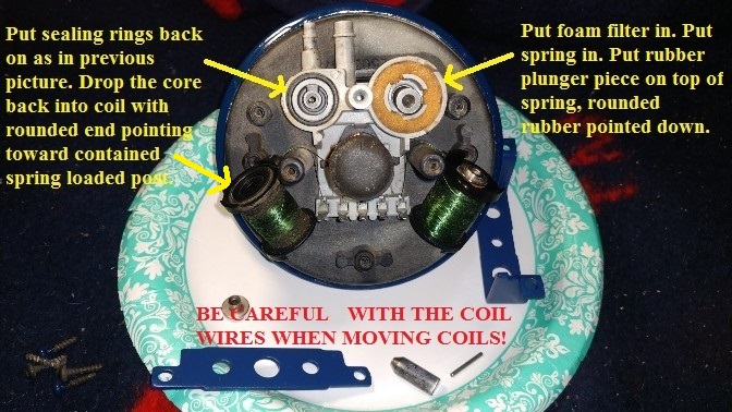
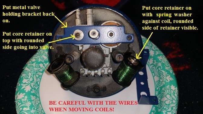
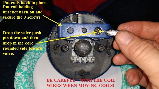
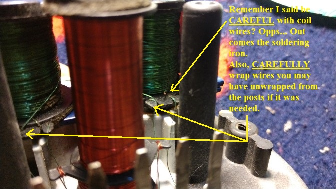
Now, I find it odd that the vent valve core doesn't have a cover. That's more rust and failure waiting to happen. But looking underneath the housing/cover, I see some indentation as if it's supposed to be hitting the cover when that solenoid is dis-engaged. That one must rust up all the time since it's exposed.
****
Found this YouTube video after my repair, and disassembled Servo again to do some more preventive maintenance on the Vacuum Valve and didn't realize the entire plastic structure can be removed from the diaphragm where there is another rubber seal I wanted to check.GM Cruise Control Vacuum Servo Actuator Repair - 1987 Buick CenturyAdded a homemade seal for the Vent Valve core/actuator.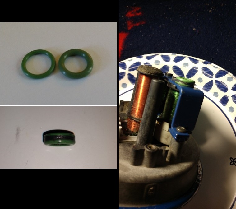 Anyone know what I should coat this with so it wont rust again, but needs to be smooth and won't wear off?
****
Installed the servo back into the bracket in the trunk and hooked everything back up. Turned ignition to 'ON'. Got the
>click< from the dump solenoid. Switched the stalk Cruise Control function to 'ON', another
>click<. Vent solenoid now operational. Turned stalk 'OFF'. Test drive time. Get my gal to 45 MPH, stalk set to 'ON'. pressed the 'SET' button.
CRUISE light on, foot off accelerator and holding. However has some hesitation, but working. Went to the interstate. Got up to 70 MPH. Worked like it should.
Success! Gonna look at vacuum issues to see what the hesitation issues are at non highway speeds. And also cylinder compression tests (man I hope the results are good if and when I do it).


