If photos have been posted before, I couldn't find them. Thought somebody might be interested.
I replace my oil pressure sender because it was exhibiting the common jiggly needle thing.
I replaced the sender (next time I'll upgrade to the 1988 connector & sender) and all is well.
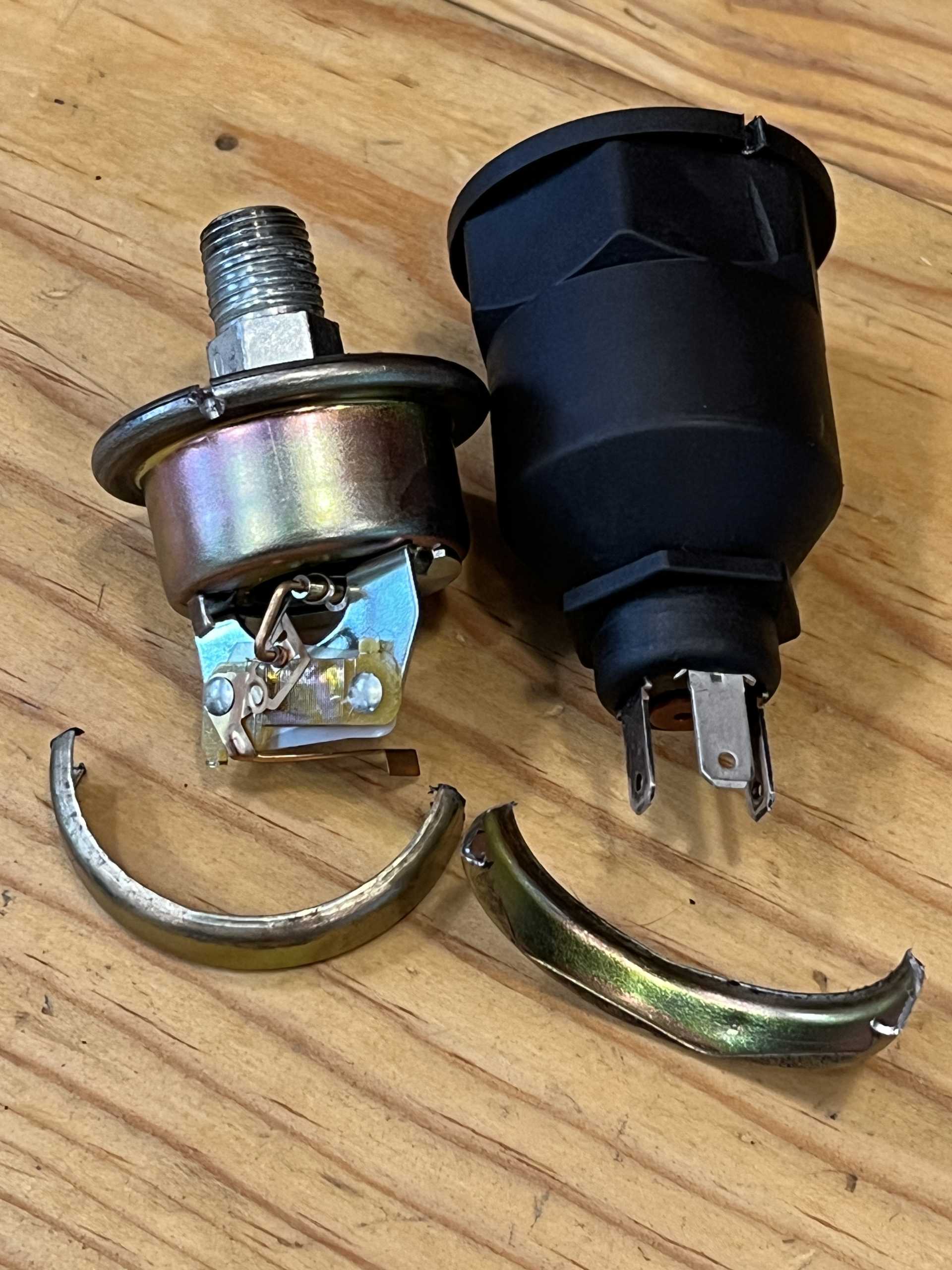
Out of curiosity, I cut open the old sender before I pitched it in the trash. Below are a couple of photos.
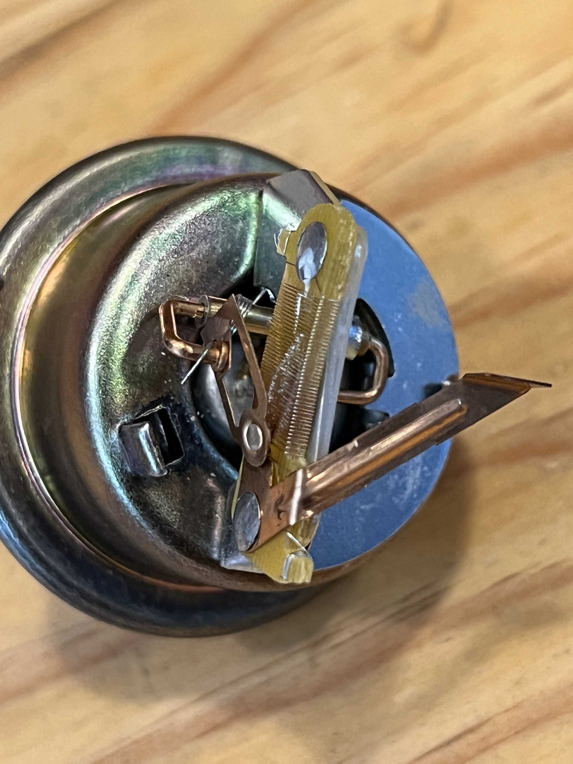
Interestingly, I saw no evidence of water infiltration. The mechanism looks quite delicate. It is a mechanical system: a diaphragm is pushed upward by oil pressure and moves a C-shaped brass connector which, in turn, rotates a contact against a wound-wire variable resistor (rheostat type). Interesting.
Presumably the 1988 sender is a modern piezoelectric type.
I never really thought about it until this thread but is the sender before or after the oil filter? If it's before, debris could get lodged in the sender opening causing these to fail.
⚠️ Warning: While the plastic case is Hex shaped & GM maybe used that to install them... Is Safer to use a 9/16" SAE wrench on the nut on the fitting. More so if your removing a good sender for other service work.
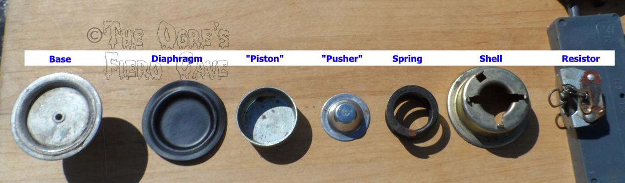
Above Pic's are good... I have one taken apart a way more years ago only some pic have posted until now. (like 1 showing base "Nut" posted several times) To get apart I had to cut the metal shell w/ Dremel cut off wheel. Lower section in order... Note: 3 small spots crimp over the resistor assembly. Larger punch-out is location for the Black Top.
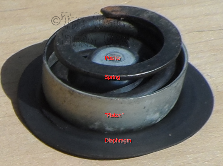
Diaphragm and others as assembled... Note: The "piston" just spreads the load over the Diaphragm. The Pusher is next then the spring. Only a small section of the Diaphragm is free to move.
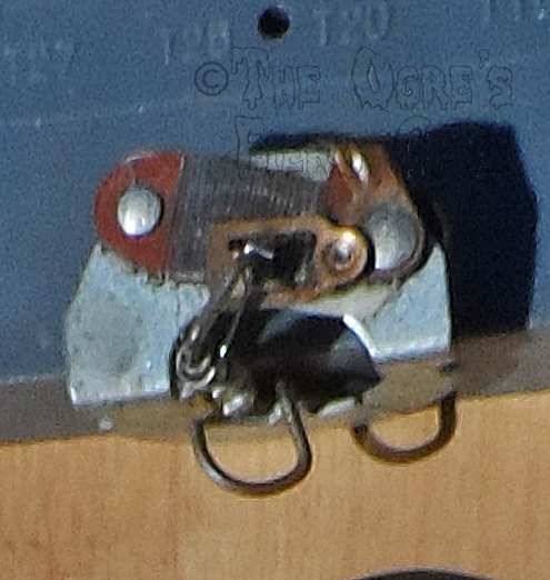
Resistor assembly showing the arm that the pusher moves/slides up...
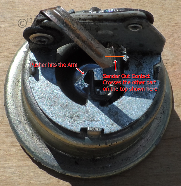
Black Top section & Upper shell w/ the resistor arm as Pusher hits...
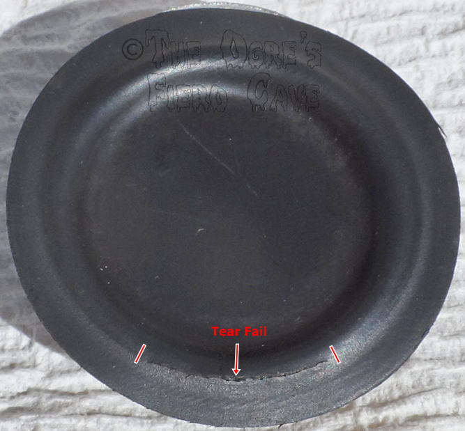
Diaphragm Failure that causes a Major Oil Leak. 2 lines are ends of the Tear.
------------------ Dr. Ian Malcolm: Yeah, but your scientists were so preoccupied with whether or not they could, they didn't stop to think if they should. (Jurassic Park)
i just replaced mine two days ago because it was pouring oil.guage still doesn't work.time to replace the circuit board on the back of the cluster.i have it already.
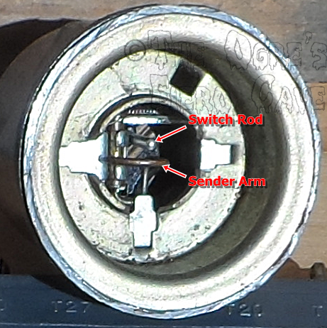
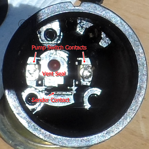
The top section... Side Note: This sender was taken apart 10+ years ago but the switch screws not until today & the switch section was still covered w/ oil inside.
The rod pushes the Fuel Pump Switch
How Sender Out Contacts works...
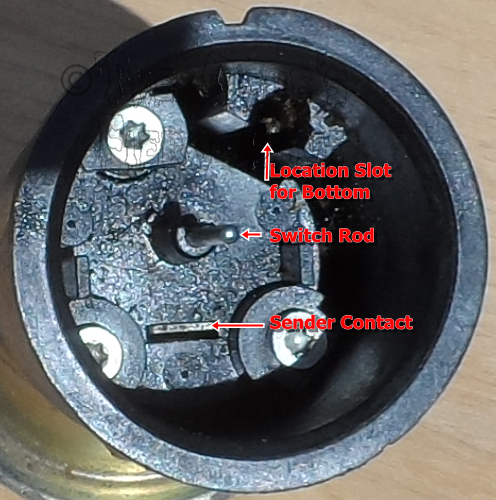
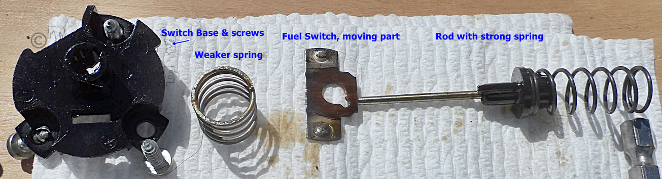
Base Removed you see this...
Base & other parts... Strong spring Opens the contacts. Weak spring just keeps all parts together. Rod & base plastics are "keyed" to keep the Switch Contact in alignment. Then the weaker spring holds the contact in place after that closes as the rod can/will move more as the piston moves more.
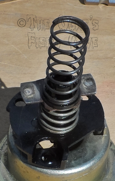
Base & parts assembled. ignore the shell as is just holding parts to take the pic here. But the rod is in the shell & hidden.
[This message has been edited by theogre (edited 06-09-2024).]
Originally posted by IMSA GT: I never really thought about it until this thread but is the sender before or after the oil filter? If it's before, debris could get lodged in the sender opening causing these to fail.
The Sender is before the filter on many engines or others after. Is likely just where they had space to mount them on a given engine.
Even mounted after the filter, Low/no Pressure is Not a filter problem for nearly all setups.
Failure cause oil leak is because Diaphragm rip like above. The "rubber" likely fails just because so little moves as the "piston" raises.
Originally posted by richard in nc: i just replaced mine two days ago because it was pouring oil.guage still doesn't work.time to replace the circuit board on the back of the cluster.i have it already.
Check the base to block w/ Ω meter. More so if you use Teflon tape to seal. Many claim that won't matter but often does block the ground enough to cause problems.
Or check Sender out pin to see has 0Ω to block because new senders can be bad.
Originally posted by Brian A: Presumably the 1988 sender is a modern piezoelectric type.
Nope. I'm told the "long" oil sender are mechanical like old type because uses 0-90Ω & very dumb 12v gauge setup but made different so won't dump the oil on the road until the pan is dry or get luck & see it leaking.
88 sender can fail for oil pressure, F-pump switch or both but not leaking problem. I & very many others have upgraded to 88 type years ago & still working so never had a dead one to dissect. I've only seen 1 leak but because the base failed from Rust. Can't find that thread & even then many pics are lost for many reason so not looking hard to find 1 post.
Other newer models have PCM/BCM to run the dash & can use piezoelectric etc as shown in How it's Made TV Show years ago & maybe still on YT or other streaming. ⚠️ Most Senders/Sensors to them have 5v. O2 sensors is 0-1v.
Some V6 & others oil sender are mounted way low where road crap can hit them. Or has AC & sender mounted high but near the Fiero Engine Vents can have same problem. That can cause rust, electrical or both problems w/ a sender or wires to it.
[This message has been edited by theogre (edited 06-09-2024).]
Nope. I'm told the "long" oil sender are mechanical like old type because uses 0-90Ω & very dumb 12v gauge setup but made different so won't dump the oil on the road until the pan is dry or get luck & see it leaking.
88 sender can fail for oil pressure, F-pump switch or both but not leaking problem. I & very many others have upgraded to 88 type years ago & still working so never had a dead one to dissect. I've only seen 1 leak but because the base failed from Rust. Can't find that thread & even then many pics are lost for many reason so not looking hard to find 1 post.
Other newer models have PCM/BCM to run the dash & can use piezoelectric etc as shown in How it's Made TV Show years ago & maybe still on YT or other streaming. ⚠️ Most Senders/Sensors to them have 5v. O2 sensors is 0-1v.
Some V6 & others oil sender are mounted way low where road crap can hit them. Or has AC & sender mounted high but near the Fiero Engine Vents can have same problem. That can cause rust, electrical or both problems w/ a sender or wires to it.
It is possible to convert to a modern piezoelectric sender but it requires a module to convert modern voltage signals into an old fashioned current "signal" for the old fashioned gauge. I was hoping the '88 sender did this internally.
I had the same problem with my Ferrari 308 QV as I do with my Fiero. The difference is that the 308 sender just eventually dies showing low oil pressure when the pressure is completely normal. Water infiltration nor oil leakage are not problems. Ferrari did a couple of good things; the oil pump is known to be extremely robust with virtually no failures ever noted and they used a second sender to trigger the low oil pressure light. The light would stay off even though the gauge showed low oil pressure.
I suppose a simplifying difference is that, on the Ferrari, there are no factory circuit boards: the sender is connected directly to the Veglia gauge via plain old wires instead of a circuit board like on the Fiero.
⚠️ Warning: "88" senders need a special wrench for them. If you don't have this, have to carefully tighten or remove them & only grab the "nut." Many think can use strap wrench etc on the plastic body but often will break now or have problems soon.
web search: 1 1/16 sensor socket The "hole" is odd shape to fit the sender. You need the "deep well" version for 88 OP sender. Other tools may work or not. Most Deep Well sockets won't work because of how there made. Never Use Impact tools even tho looks like other impact sockets.
quote
Originally posted by Frenchrafe: Yep! The '88 sensor is the same variable restance type. I had a leaking one recently and when I do the "autopsy" you can see the resistance: <snip>
Thanks, Video shows enough to some is "same thing w/ different package."
that's only 2nd time one leaked... But w/ old type, many had them Fail & leaked every few years before using the "88" sender. Even if not driving much last me ~ 3 years & replace several times but "88" is 10+ years.
Today I found a video cut apart to see it working or not in when gets stuck... How an Oil Sender works https://www.youtube.com/watch?v=c2igtCvCNwA after 5:30. I think the wire diagram shown is for different model or other trim level for same vehicle so ignore that part showing the OP Warning Switch.
[This message has been edited by theogre (edited 06-10-2024).]
Originally posted by Brian A: It is possible to convert to a modern piezoelectric sender but it requires a module to convert modern voltage signals into an old fashioned current "signal" for the old fashioned gauge. I was hoping the '88 sender did this internally.
GM & more didn't bother because of cost. Just wanted to update X part w/ minimum cost etc. I'm surprise can even get the old style OP Sender like can't get old ECT sensors at all even 20+ years ago so when need to buy new sensor have to get a new Metricpack Plug too. GM had a lot of problems w/ the old round plug.
Can mod the wiring etc for other types but most people including all repair shops just want whatever fix w/ minimum work too. Maybe that why can get this old part but not ECT because 5v sensor & ECM/PCM is very picky about resistance.
But even the "short" OP sender w/ piezoelectric guts or just controls OP warming light have same base can have same problems w/ rust "water" etc. attack to sender or wires to it.
[QUOTE]Originally posted by richard in nc: i just replaced mine two days ago because it was pouring oil.guage still doesn't work.time to replace the circuit board on the back of the cluster.i have it already.
Check the base to block w/ Ω meter. More so if you use Teflon tape to seal. Many claim that won't matter but often does block the ground enough to cause problems.
Or check Sender out pin to see has 0Ω to block because new senders can be bad.[/QUOTE]
it was a 'standard'sender which came with the sealer on it.the reason it was leaking is i pulled the plug off to ground it out to check the guage.it didn't move.i think the 'moving' of a 37 yo part broke it.
⚠️ Warning: "88" senders need a special wrench for them. If you don't have this, have to carefully tighten or remove them & only grab the "nut." Many think can use strap wrench etc on the plastic body but often will break now or have problems soon.
web search: 1 1/16 sensor socket The "hole" is odd shape to fit the sender. You need the "deep well" version for 88 OP sender. Other tools may work or not. Most Deep Well sockets won't work because of how there made. Never Use Impact tools even tho looks like other impact sockets.
[QUOTE]Originally posted by Frenchrafe: Yep! The '88 sensor is the same variable restance type. I had a leaking one recently and when I do the "autopsy" you can see the resistance: <snip>
Thanks, Video shows enough to some is "same thing w/ different package."
that's only 2nd time one leaked... But w/ old type, many had them Fail & leaked every few years before using the "88" sender. Even if not driving much last me ~ 3 years & replace several times but "88" is 10+ years.
Today I found a video cut apart to see it working or not in when gets stuck... How an Oil Sender works https://www.youtube.com/watch?v=c2igtCvCNwA after 5:30. I think the wire diagram shown is for different model or other trim level for same vehicle so ignore that part showing the OP Warning Switch.
[/QUOTE] if i had a 1 5/8" deeep socket my 1987 sender would have been easy to change.instead i had to bend a cheepy 9/16.
Thanks, Video shows enough to some is "same thing w/ different package."
that's only 2nd time one leaked...
Yes, well it lasted 10 years with harsh driving (trackdays), 1 engine fire (drive shaft boot failure and grease on the exhaust, all very close to the sensor) and one engine rebuild! Let's hope that this one does as well...
------------------ "Turbo Slug" - '87 Fiero GT. 3800 turbo. - The fastest Fiero in France! @turboslugfiero https://youtu.be/hUzOAeyWLfM