Hey guys, long story short... I'm replacing the fuel sending unit connector in my daughter's 85 Fiero 2m4 SE. She replaced the fuel ending unit, and of course it came with a new connector. The vehicle side of the connector that connects to the ECM / vehicle side... that was really jacked up.. to the point that it was barely held together.
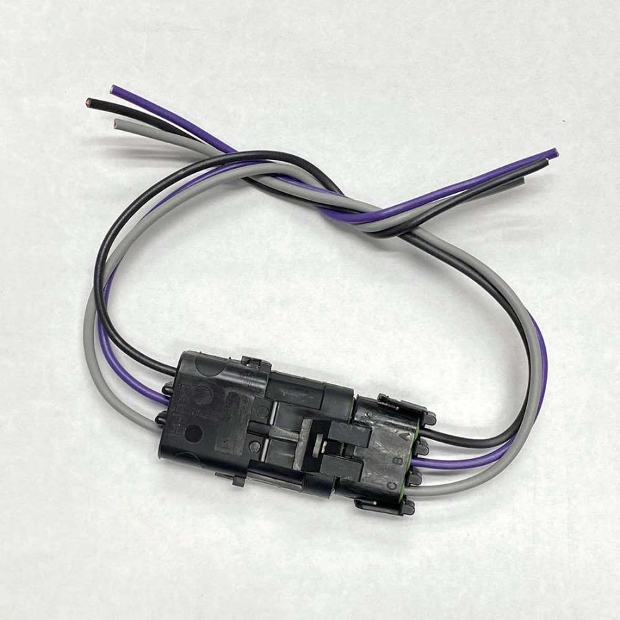
So, I bought this kit:
I obviously only needed one side of it, since the fuel sending unit already had a nice one.
Anyway, as I was splicing into the factory harness, I tugged a little bit on the new connector as I was stripping it, and the wire pulled right now. I then tugged the others, and they pulled directly out too. Basically, these had never been soldered in. I'm super frustrated, because how can these connectors be sold without the wires being soldered in?
Anyway, I now have a useless connector, and I'm trying to figure out where to go from here. Is there any way to remove the three metal pins / prongs from within the connector, so that I can reuse them and properly solder them in like they should have been?
You can purchase a connector pin removal tool. You choose the proper size on the tool, insert it and press on the catch tab of the pin. The wire with the connection pin depressed can be easily released with the wire attached. Then you insert in back into the new connector housing in the same spot and move on and to the next pin. That tool can be purchased on eBay or Amazon for under $10.
------------------ " THE BLACK PARALYZER" -87GT 3800SC Series III engine, custom ZZP /Frozen Boost Intercooler setup, 3.4" Pulley, Northstar TB, LS1 MAF, 3" Spintech/Hedman Exhaust, P-log Manifold, Autolite 104's, MSD wires, Custom CAI, 4T65eHD w. custom axles, Champion Radiator, S10 Brake Booster, HP Tuners VCM Suite. "THE COLUSSUS" 87GT - ALL OUT 3.4L Turbocharged engine, Garrett Hybrid Turbo, MSD ign., modified TH125H " ON THE LOOSE WITHOUT THE JUICE "
[This message has been edited by Dennis LaGrua (edited 10-16-2024).]
Did you mean the wire pulled out leaving the connector still in the plug housing ?
Yes, totally infuriating...
quote
Originally posted by cliffw:
I correctly bent paper clip works for me. Might need the right sized paper clip.
There is a tab on each of the wire's "plug". Pull the wire out, bend the tab upward, and it will lock in place when reinserted.
I already ordered the one from Amazon. I've done something similar before in all kinds of other connectors... but in these GM ones (or faux GM ones), it seemed totally impossible. At least now I can fix this one and solder it in.
Originally posted by 82-T/A [At Work]: Anyway, as I was splicing into the factory harness, I tugged a little bit on the new connector as I was stripping it, and the wire pulled right now. I then tugged the others, and they pulled directly out too. Basically, these had never been soldered in. I'm super frustrated, because how can these connectors be sold without the wires being soldered in?
Anyway, I now have a useless connector, and I'm trying to figure out where to go from here. Is there any way to remove the three metal pins / prongs from within the connector, so that I can reuse them and properly solder them in like they should have been?
Soldering is not normally used in automotive wiring harnesses, as solder can create an inflexible hard point where a breakage could occur with movement.
Crimping is the best method.
If the wires pulled out of the crimp easily, the crimp was not done correctly. Perhaps the crimp terminal was for the incorrect wire gauge, or the tool didn't squish the crimp right.
The fuel sending unit connector (along with many other connectors in the Fiero) is from the Delphi Weather-Pack series.
Originally posted by cliffw: I correctly bent paper clip works for me. Might need the right sized paper clip.
Weather-Pack uses a tube-shaped depinning tool. It squeezes the tabs on opposite sides of the terminal together to release it from the plastic housing.
A paper clip can sometimes work for other types of terminals with a single retaining tab.
Weather-Pack uses a tube-shaped depinning tool. It squeezes the tabs on opposite sides of the terminal together to release it from the plastic housing.
A paper clip can sometimes work for other types of terminals with a single retaining tab.
Yeah, I figured there was a way to do it... but I didn't even know what the tool was called. In the past, with computer connectors and other things, I've just used a paper-clip to pull the tab back. Even on Molex connectors (computers) those tabs are easier to see and I can just squeeze a small flat-blade screwdriver in there. But these connectors, with it getting harder to see up close now that I'm in my 40s, I couldn't see anything that I could reach. Really cool that these tools exist.
As for the connectors... ugh... this was an aftermarket connector that I was using to replace a completely damaged original connector... the original connector was so damaged that one of the leads could pull right out. The wires were also cracked and damaged at the end too... so I needed to cut them anyway. But the replacement connector was aftermarket... the wiress pulled out with no effort at all. Like, they literally pulled out while I was using the wire stripper on the leads. :/
In the past, I've crimped and THEN soldered both ends of the crimp. Is this not a good thing?
Originally posted by 82-T/A [At Work]: In the past, I've crimped and THEN soldered both ends of the crimp. Is this not a good thing?
What do you mean about soldering both ends of the crimp? Wouldn't you only solder the crimped area where the wire strands are squished?
If you're not confident in your crimping setup, then I guess you could also solder. However, there is a risk of corrosion due to the soldering flux residues (which cannot be washed inside the wire). With rosin mildly activated flux-core soldering wire, the corrosion risk is probably not too great. Also, the solder may wick and flow into the wire, and create a hard spot in the unsupported portion of the wire (where it may be subject to flexing), outside of the connector.
Before crimping a terminal for use in the car, it is wise to to some test crimps first. Hold the terminal in a vise, and then tug on the wire. The strands should break, and not slide out of the crimp. If you have the correct good technique, tools, and parts, you can check your work in this way.
For splices in the wiring harness, you can use open-barrel crimp splices. Here are some wire harness splices that I did when I replaced a connector+pigtail on my Ford Ranger: https://www.fieromontreal.c...86.msg34687#msg34687
Since I gained confidence with the successful repair on my Ford Ranger, I felt comfortable with using open-barrel crimp splices on my Fiero.
FYI, the Fiero (and many OEM cars) use open-barrel crimp splices in their wire harnesses.
[This message has been edited by pmbrunelle (edited 10-15-2024).]
What do you mean about soldering both ends of the crimp? Wouldn't you only solder the crimped area where the wire strands are squished?
If you're not confident in your crimping setup, then I guess you could also solder. However, there is a risk of corrosion due to the soldering flux residues (which cannot be washed inside the wire). With rosin mildly activated flux-core soldering wire, the corrosion risk is probably not too great. Also, the solder may wick and flow into the wire, and create a hard spot in the unsupported portion of the wire (where it may be subject to flexing), outside of the connector.
Before crimping a terminal for use in the car, it is wise to to some test crimps first. Hold the terminal in a vise, and then tug on the wire. The strands should break, and not slide out of the crimp. If you have the correct good technique, tools, and parts, you can check your work in this way.
For splices in the wiring harness, you can use open-barrel crimp splices. Here are some wire harness splices that I did when I replaced a connector+pigtail on my Ford Ranger: https://www.fieromontreal.c...86.msg34687#msg34687
Since I gained confidence with the successful repair on my Ford Ranger, I felt comfortable with using open-barrel crimp splices on my Fiero.
FYI, the Fiero (and many OEM cars) use open-barrel crimp splices in their wire harnesses.
I'm getting confused on what you're asking me. The crimps that pulled out... I didn't do those. See the picture I posted above. Both ends of the harness came like that. I didn't need the male part, only the female end of the connector. I pulled lightly on the wires as I was stripping the wire end, and it literally pulled out of the connector (with the green seal attached). A slight tug on the other two, and the same thing happened. Whomever put them together did a horrible job (and sold them like that).
I've never had a wire pull out on something I've crimped... not that I'm an expert in wire crimping. But I used to not use solder when I would re-wire a car. I'd just use a crimping tool. If I think the wire is going to be under a lot of stress, I take the wire past the crimped area, crimp it, and then fold the wires back over, and then solder the front and back of it, and then cover it with heat shrink. Otherwise, I usually only soldier joined wires.
EDIT: Those crimps look good. Any reason why you wouldn't want to add just a little bit of solder at both ends?
[This message has been edited by 82-T/A [At Work] (edited 10-15-2024).]
Originally posted by 82-T/A [At Work]: In the past, I've crimped and THEN soldered both ends of the crimp. Is this not a good thing?
quote
Originally posted by pmbrunelle: What do you mean about soldering both ends of the crimp? Wouldn't you only solder the crimped area where the wire strands are squished?
quote
Originally posted by 82-T/A [At Work]: I'm getting confused on what you're asking me. The crimps that pulled out... I didn't do those. See the picture I posted above. Both ends of the harness came like that. I didn't need the male part, only the female end of the connector. I pulled lightly on the wires as I was stripping the wire end, and it literally pulled out of the connector (with the green seal attached). A slight tug on the other two, and the same thing happened. Whomever put them together did a horrible job (and sold them like that).
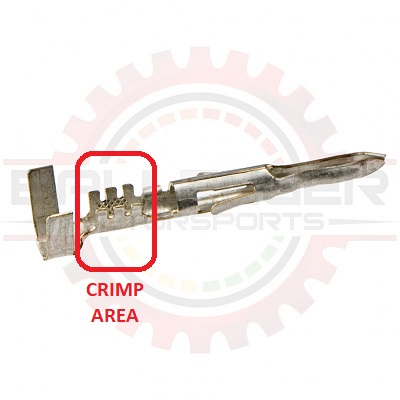
On a crimp terminal, there is only one area which can be crimped (and maybe soldered), and it is in the middle, not the ends.
I do not understand what you meant about soldering both ends of the crimp.
quote
Originally posted by 82-T/A [At Work]: EDIT: Those crimps look good. Any reason why you wouldn't want to add just a little bit of solder at both ends?
I would not add solder, because it would create a hard spot in the wire harness (well, harder than the open-barrel crimp splice).
In automotive, we use stranded wires because they are more flexible and resilient with respect to bending, vibration, etc. Solid conductor wiring (like we use in homes) would not be reliable. With the solder wicking into the wire, you are effectively creating a solid-conductor section of wiring, which is not flexible. Worse than a solid-conductor wire, is a wire that suddenly changes from solid to stranded; the transition point tends to be a weak spot.
[This message has been edited by pmbrunelle (edited 10-15-2024).]
Originally posted by pmbrunelle: On a crimp terminal, there is only one area which can be crimped (and maybe soldered), and it is in the middle, not the ends.
I do not understand what you meant about soldering both ends of the crimp.
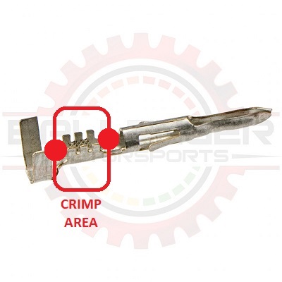
Here, I would add a little bit of solder in the front and in the back of it, where I put the red dots.
I just want to be clear, I wasn't the one who crimped these wires. I basically bought a pigtail harness that I'd intended to splice into my existing harness because the factory connectors (and the wires themselves just before the connector), were totally trashed. When I went to strip the wire ends on the new harness + connector, the wires literally pulled out of the connector... I was friggin' pissed. I'd never seen anything like that. I thought maybe it was a fluke, so I barely tugged on the other two, and the other two pulled out with almost no effort at all.
quote
Originally posted by pmbrunelle: I would not add solder, because it would create a hard spot in the wire harness (well, harder than the open-barrel crimp splice).
In automotive, we use stranded wires because they are more flexible and resilient with respect to bending, vibration, etc. Solid conductor wiring (like we use in homes) would not be reliable. With the solder wicking into the wire, you are effectively creating a solid-conductor section of wiring, which is not flexible. Worse than a solid-conductor wire, is a wire that suddenly changes from solid to stranded; the transition point tends to be a weak spot.
Ok, I get this. On the Fiero, (at least my daughter's Fiero), there is a double-loop connector that has two red power wires that are soldered into it... which I believe is from the factory. It connects to the power distribution block that's under the C500 connector. It's the only place I've ever seen anything soldered. Never the less... the wires literally broke at the solder point. I don't know if you know the one I'm talking about. I can't seem to find a replacement "double-loop" crimp connector either... so I'm going to have to use two single-loop crimp connectors, and then use the old double-loop connector (with the end cut off) as the connector for the two power posts (which is part of what it was supposed to do originally).
In the past, I've only ever crimped wires, never soldered... but when I'd mentioned it, people would swear up and down I needed to add a little bit of solder on the crimp connectors because blah blah, it would pull out, etc., etc. So, I just recently started doing that... but I haven't had to do too much repair. I don't use a whole lot, I've got really fine solder that I use for when I'm working on circuit boards and doing through-hole stuff (like repairing an arcade PCB or something). Even in the connector, you don't think just a little bit front and back (like what I showed above with the red dots) would be a bad thing? Or are you just saying it's unnecessary? In the case of the above crimp connector, it wouldn't create a hard point per-se because you'd still have the clamp at the back for holding the sheathed wire. Any thoughts on this?
Originally posted by pmbrunelle: Also, the solder may wick and flow into the wire, and create a hard spot in the unsupported portion of the wire (where it may be subject to flexing), outside of the connector.
quote
Originally posted by 82-T/A [At Work]: Here, I would add a little bit of solder in the front and in the back of it, where I put the red dots.
I suspect you have poor soldering technique (and hence do not understand how solder is supposed to wick).
Wicking means that once the copper wiring reaches the melting point of the solder, the metal of the solder melts, and then flows along (wicks) onto the metal surfaces that are sufficiently hot. So, the solder will travel for some distance.
If you are able to put two distinct dots of solder, it sounds like cold-soldered globs that do nothing.
In the beginning of this video, there are poor examples with distinct globs, and then at the end there are good examples of a soldered joint: https://www.youtube.com/watch?v=4xUBRMgcVhc
quote
Originally posted by 82-T/A [At Work]: Even in the connector, you don't think just a little bit front and back (like what I showed above with the red dots) would be a bad thing? Or are you just saying it's unnecessary? In the case of the above crimp connector, it wouldn't create a hard point per-se because you'd still have the clamp at the back for holding the sheathed wire. Any thoughts on this?
I think that a good soldering joint is not necessary from a conductivity point of view, although it won't hurt. The main bottleneck (from an electrical resistance point of view) is the contact between the male and female terminals of the connector.
If you have a properly-wetted solder joint, the solder may go further than the clamped area (yes, solder can wick and continue under insulation). This is a possible risk.
If you have a poorly-done solder joint, then I don't know