you're working on alot of modifications to your car all at once already, from my experience, I would try to narrow your focus to the engine/transmission swap, then work on other things once the car runs and drives again, the snowball can very quickly derail your build and then you end up with a 10 year old build that's barely been driven (like mine).
Good luck
-Eric
Yeah, that's for later spring/early summer, I've always worked best when I have clear paths planned out for basically everything, so yeah, I'm not getting wheels until it is a running, driving vehicle (and needs better tires), I just plan ahead so it doesn't take me time to decide when I do actually want them.
Well I finally got to the point where I could start the engine today, I had already been playing with the tune for the last few months out of the car, to get it as close as possible to useable before having to actually try and start the car, turns out that paid off, it started the first time I turned the key!
Oh and for now I'm using the 3400 VR crank sensor, directly wired to the megasquirt, the 3400 hall effect Cam position sensor, wired to the megasquirt on digital frequency in 2, and I'm using the original Fiero ICM to connect to the coil, with gm 7x settings in the megasquirt, which does not include the bypass signal, so under the on/off outputs, I have a spare spark out wire set to turn on when rpm is > 400 or something like that, just as the original ECM did. Turning the distributor will adjust the non bypassed (cranking) spark advance (running off the ICM), but not the megasquirt commanded spark advance.
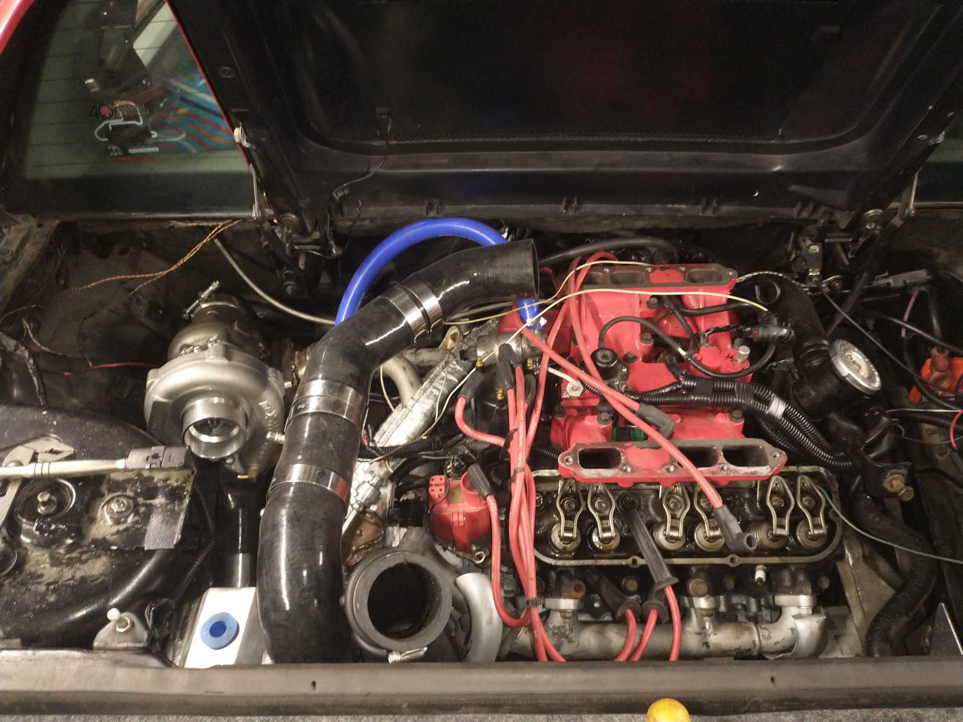
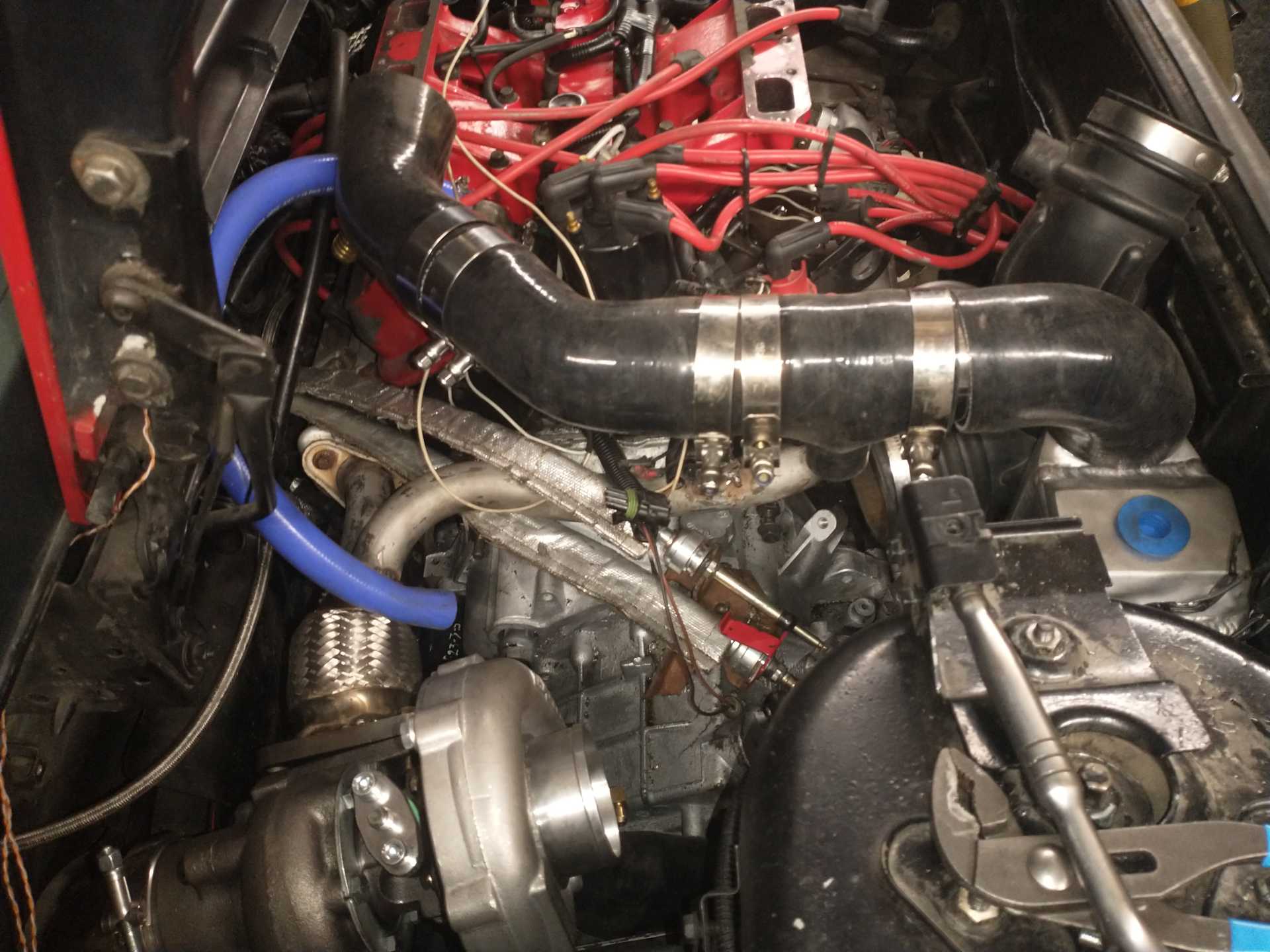
More progress, I'm finishing the exhaust and the routing of the intake, seems like it will all work just fine.
From the turbo to the water/air intercooler, it runs down between the transmission and the frame rail, then goes into the bottom of the Intercooler, from there it goes from the top to the throttle body.
More wiring today (yesterday now I guess), got the reverse switch wired, got the speedometer working (f23 speedo in to ECM on the cam in wires, 4000 ppm speedo out on digital frequency 1, through a 1.2μf capacitor from the tweeter of an old bookshelf speaker to the yellow speedometer high wire going to the dash. Hooking it up directly did not work, speedo is expecting the AC signal from a VR style sensor, not the switched DC of the ECM output, and apparently a simple capacitor in line fixes that).
Also removed the reverse lockout from my 4 speed shifter, and the "centering spring" (holds the shifter in the far right position as default)
Megasquirt has an option to fully open the IAC valve during WOT, I'm using a Porsche/Bosch/PWM 3/4" hose IAC valve, sitting where the EGR tube would be, running into the lower intake IAC passage, then will be going into a port on the intake tubing before the throttle body (the blue tube in pictures). Would this be beneficial? In theory it would allow a decent bit of air to bypass the restrictive upper intake (3/4"all the way to the lower intake, then reduced to the 1/2" barb there, then the IAC passages), unless airflow is so unevenly distributed to cause issues, or it adds turbulence to the main stream that slows everything down. Thoughts on this? I would assume it would be somewhat well balanced, especially with the cold start injector in there (from factory, I'm not using it any more), you'd think that would be designed to be distributed fairly evenly, but who knows.
Originally posted by 1985 Fiero GT: Megasquirt has an option to fully open the IAC valve during WOT, I'm using a Porsche/Bosch/PWM 3/4" hose IAC valve, sitting where the EGR tube would be, running into the lower intake IAC passage, then will be going into a port on the intake tubing before the throttle body (the blue tube in pictures). Would this be beneficial? In theory it would allow a decent bit of air to bypass the restrictive upper intake (3/4"all the way to the lower intake, then reduced to the 1/2" barb there, then the IAC passages), unless airflow is so unevenly distributed to cause issues, or it adds turbulence to the main stream that slows everything down. Thoughts on this? I would assume it would be somewhat well balanced, especially with the cold start injector in there (from factory, I'm not using it any more), you'd think that would be designed to be distributed fairly evenly, but who knows.
I guess it would partially depend on how quickly the IAC goes from full open to full close. When you do WOT upshifts you will likely not want a 3/4" opening to stay open or you could likely hit the rev limiter.
With boost, the neck of the plenum will be less of an issue (just add more boost) or do the Dawg neck modification. I would do the Dawg mod simply to help remove the restriction. While you can add more boost, it would come at a penalty of more heat, which would need to be addressed. For my build, it I focused on making everything up stream of the cylinders as free flowing as possible to maximize hp with the least amount of boost/heat.
Creating and using a large air path from the the air intake track around the throttle body and into the runners, will skew the readings from the MAP sensor in the plenum. It will shift the readings higher (higher kPa) because the plenum will see less vacuum than what is present in the runners between the cylinders and the cold start ports. Having the IAC wide open will magnify the issue.
Loudias did a modification to the lower intake where he created a slot between the runner walls at the lower to middle intake gasket surface to allow some airflow equalization between runners. This showed something like a 20 hp improvement on the dyno. I would consider this modification vs. the IAC mod.
It's a PWM solenoid, so I would assume pretty fast, I would also think megasquirt would release it as soon as TPS gets under x percent, where my foot would still be releasing the throttle, and that is not an instantaneous event either.
Yes that's one reason why I'm doing all this, 3.4 and a turbo, I don't want an engine that falls on its face due to a choked air supply (non turbo 3.4), and I will not give up the Fiero intake, so a turbo just blows right through the restriction and as a benefit makes even more power everywhere else. I was hesitant to do that on the 2.8 and 3.4 firebird engines because of reliability concerns, but the 3400 is stronger so seems a perfect match. I will not be doing the dawg mod, I can't weld aluminum (still learning to do exhaust haha), and anywhere near me would charge an arm, a leg, and take a kidney for spite, small towns in the middle of nowhere where services charge a premium, last year I got an exhaust manifold crack welded, 2" weld cost nearly $200, and I had the part cleaned and prepped already. I've sent my intake off to Quebec, Quebec to be powder coated, still expensive, but I'm tired of dealing with bad paint adhesion (failed paint twice already).
I didn't think of the map sensor, but being only at wide open throttle, how will it act with boost, I mean theoretically with an open throttle, x amount of boost, it's just going to be pretty much equalised through the intake, I don't know how sensitive this is though.
Would it even be a problem? If the map reads higher, but that is because more air is getting into the engine, wouldn't that make sense? When you open your throttle more, the map reads higher, more air is getting into the engine, IAC opens, more air goes to the heads, less vacuum to the plenum, which reads as higher map, that's expected, what would this do that it isn't supposed to. More air=less vacuum, would this setup amplify that? (10 units sucked in by throttle, 1 by IAC, would it read as 10% higher on the map, because that would be true, or more than that?)
I won't be doing that mod at the moment, maybe after more research, but the middle intake is already on, and I'm trying to get finished haha.
Originally posted by 1985 Fiero GT: More wiring today (yesterday now I guess), got the reverse switch wired, got the speedometer working (f23 speedo in to ECM on the cam in wires, 4000 ppm speedo out on digital frequency 1, through a 1.2μf capacitor from the tweeter of an old bookshelf speaker to the yellow speedometer high wire going to the dash. Hooking it up directly did not work, speedo is expecting the AC signal from a VR style sensor, not the switched DC of the ECM output, and apparently a simple capacitor in line fixes that).
Direct Current, or DC, is a misnomer; in French it is called Courant Continu, or CC. Continous current you could say.
DC means unchanging over time.
If the DC is switched, then it is no longer purely DC; it is DC with an alternating (AC) component added on top.
Capacitors block DC current, as there is no electrical connection between both electrodes. However, AC current can pass through capacitors, as electrical charges on one electrode can attract/repel charges on the other electrode for short durations.
quote
Originally posted by 1985 Fiero GT: Also removed the reverse lockout from my 4 speed shifter, and the "centering spring" (holds the shifter in the far right position as default)
I'm planning on keeping my centering spring in the shifter (but messing with the springs in the F23 to make everything work); I think that it will help enhance shifter feel and mask the feeling of backlash in the mechanism.
quote
Originally posted by 1985 Fiero GT: Megasquirt has an option to fully open the IAC valve during WOT, I'm using a Porsche/Bosch/PWM 3/4" hose IAC valve, sitting where the EGR tube would be, running into the lower intake IAC passage, then will be going into a port on the intake tubing before the throttle body (the blue tube in pictures). Would this be beneficial? In theory it would allow a decent bit of air to bypass the restrictive upper intake (3/4"all the way to the lower intake, then reduced to the 1/2" barb there, then the IAC passages), unless airflow is so unevenly distributed to cause issues, or it adds turbulence to the main stream that slows everything down. Thoughts on this? I would assume it would be somewhat well balanced, especially with the cold start injector in there (from factory, I'm not using it any more), you'd think that would be designed to be distributed fairly evenly, but who knows.
I think that you can work this out later when testing/tuning the car on the road.
If you are running in open-loop, and during a pull the measured AFR is leaner than before the change, then whatever you did increased airflow.
quote
Originally posted by 1985 Fiero GT: Yes that's one reason why I'm doing all this, 3.4 and a turbo, I don't want an engine that falls on its face due to a choked air supply (non turbo 3.4), and I will not give up the Fiero intake, so a turbo just blows right through the restriction and as a benefit makes even more power everywhere else.
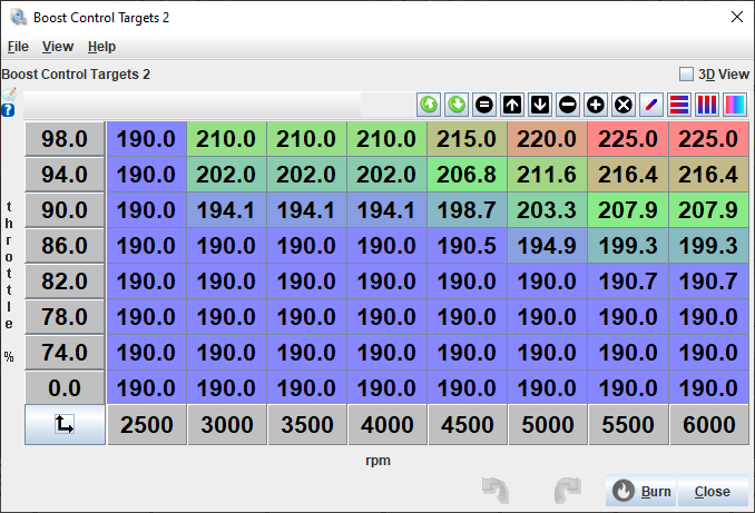
I haven't done this yet, but I'm planning on having a boost target that rises with RPM to help mask the restrictive nature of the stock intake. The car drives ok with constant boost pressure, but I think that rising boost with RPM could help make things feel a bit more linear.
[This message has been edited by pmbrunelle (edited 03-05-2025).]
Direct Current, or DC, is a misnomer; in French it is called Courant Continu, or CC. Continous current you could say.
DC means unchanging over time.
If the DC is switched, then it is no longer purely DC; it is DC with an alternating (AC) component added on top.
Capacitors block DC current, as there is no electrical connection between both electrodes. However, AC current can pass through capacitors, as electrical charges on one electrode can attract/repel charges on the other electrode for short durations.
I'm planning on keeping my centering spring in the shifter (but messing with the springs in the F23 to make everything work); I think that it will help enhance shifter feel and mask the feeling of backlash in the mechanism.
I think that you can work this out later when testing/tuning the car on the road.
If you are running in open-loop, and during a pull the measured AFR is leaner than before the change, then whatever you did increased airflow.
I haven't done this yet, but I'm planning on having a boost target that rises with RPM to help mask the restrictive nature of the stock intake. The car drives ok with constant boost pressure, but I think that rising boost with RPM could help make things feel a bit more linear.
Yeah, makes sense, it took an afternoon to wrap my head around how the capacitor can generate a negative voltage when the 5v is turned off, it seemed to easy of a solution haha, another note, I never realized how loud the speedometer/odometers are, they click and whir, which you don't hear when the engine is running and you're driving, but stationary with the megasquirt outputting a test signal, it was alarming the first time I did it haha.
Yeah I saw that, I'm not going to fiddle with that until after I can feel what it feels like with nothing additional.
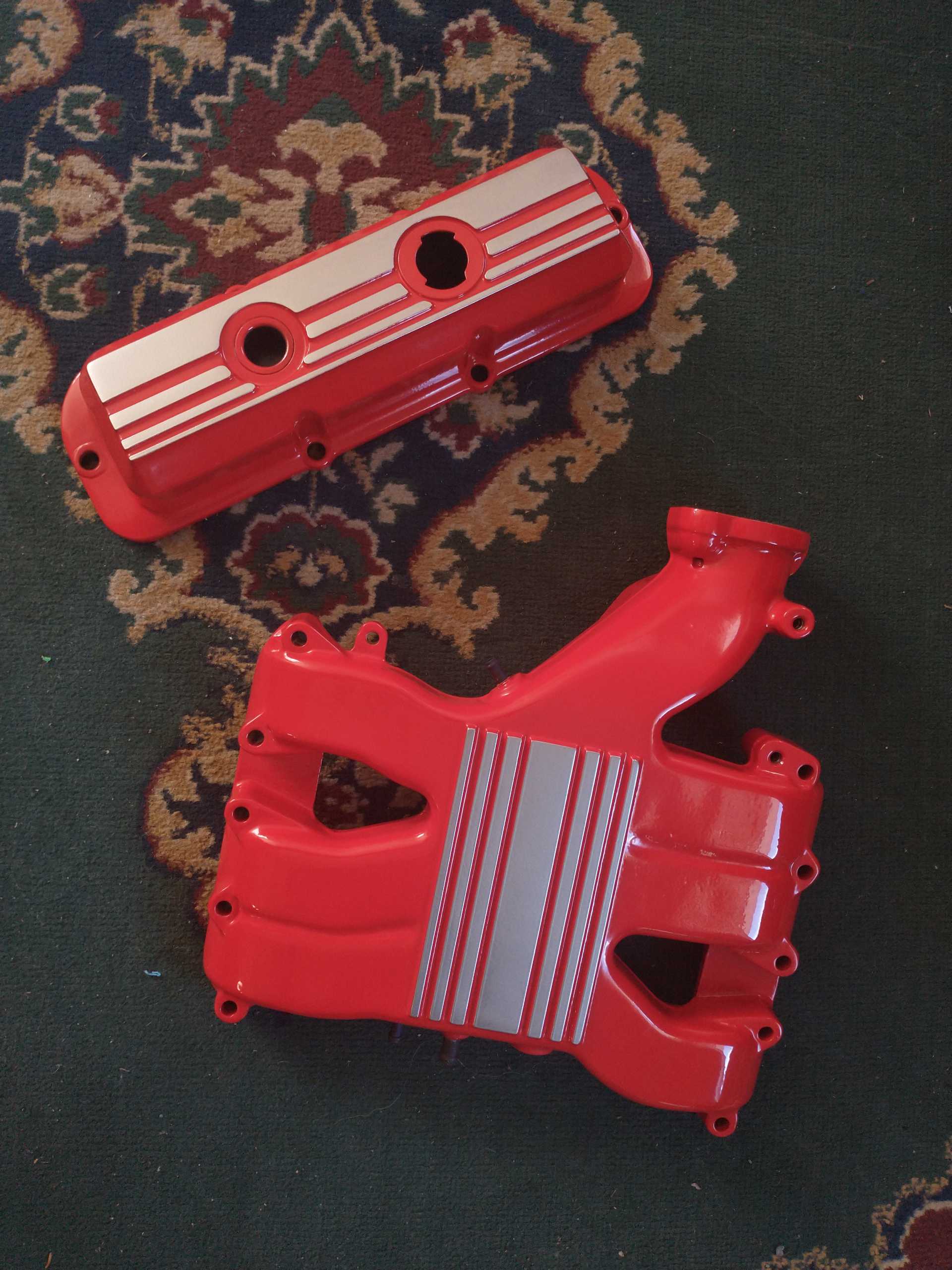
I got my intake and valve cover back from being powder coated, Chevy Torch Red, satin silver, and clear over all that, they look beautiful! Cost was about $500cad, best price I could find.
Did a compression test on all cylinders when I removed the spark plugs to gap them smaller, I cranked it 5 pulses, and recorded the gauge while I did that.
So I have one cylinder that's a little low (it had been lower, 100 psi, but I re-tested it after all the others, and it had improved to 110), one that's a little high (that is the one I removed the piston to check the ring gaps, I had oiled it up to put it back in) remember this is a junkyard 3400 that has run maybe 2 minutes in the last several years or more, and was stone cold, so perhaps cyl 1 will improve with time, I will check it again after it has gotten back on the road. Test was done with no upper intake, battery on charger, no fuel or spark, all plugs removed the entire test.
Originally posted by 1985 Fiero GT: So I have one cylinder that's a little low (it had been lower, 100 psi, but I re-tested it after all the others, and it had improved to 110), one that's a little high (that is the one I removed the piston to check the ring gaps, I had oiled it up to put it back in) remember this is a junkyard 3400 that has run maybe 2 minutes in the last several years or more, and was stone cold, so perhaps cyl 1 will improve with time, I will check it again after it has gotten back on the road. Test was done with no upper intake, battery on charger, no fuel or spark, all plugs removed the entire test.
If you have a low compression hole now, you will later too. as cheap as these engines are, I would either find another, or start measuring components and looking into machine work for a rebuild.
------------------ "I am not what you so glibly call to be a civilized man. I have broken with society for reasons which I alone am able to appreciate. I am therefore not subject to it's stupid laws, and I ask you to never allude to them in my presence again."
I invited Lou Dias to trash me in my own thread, he refused. sorry. if he trashes your thread going after me. I tried.
If you have a low compression hole now, you will later too. as cheap as these engines are, I would either find another, or start measuring components and looking into machine work for a rebuild.
I can get another one easily enough if needed, but from some quick research it isn't uncommon to have a low compression cylinder after "sitting" for years, thats just old carbon, dirt etc. keeping the rings or valves from sealing on a cylinder that may have had a valve open for that time, that is something that can clear itself out mostly and resolve itself once the engine is running/oil is getting everywhereits needed. In 50 rotations of the engine (5 other cylinders tested, 5 pulses per test), compression improved by over 10% between the first and second time I tested that cylinder. I will test the 3 rear cylinders again once I've had the engine running a couple heat cycles, cyl 1 to see if the compression has improved, cyl 3 as a control, and cyl 5 to see the real number without being effected by extra oil.
I got my intake and valve cover back from being powder coated, Chevy Torch Red, satin silver, and clear over all that, they look beautiful! Cost was about $500cad, best price I could find.
Weather turbo or not these 60 degree engines want plenum and runner volume. The stock parts you are using lack both.
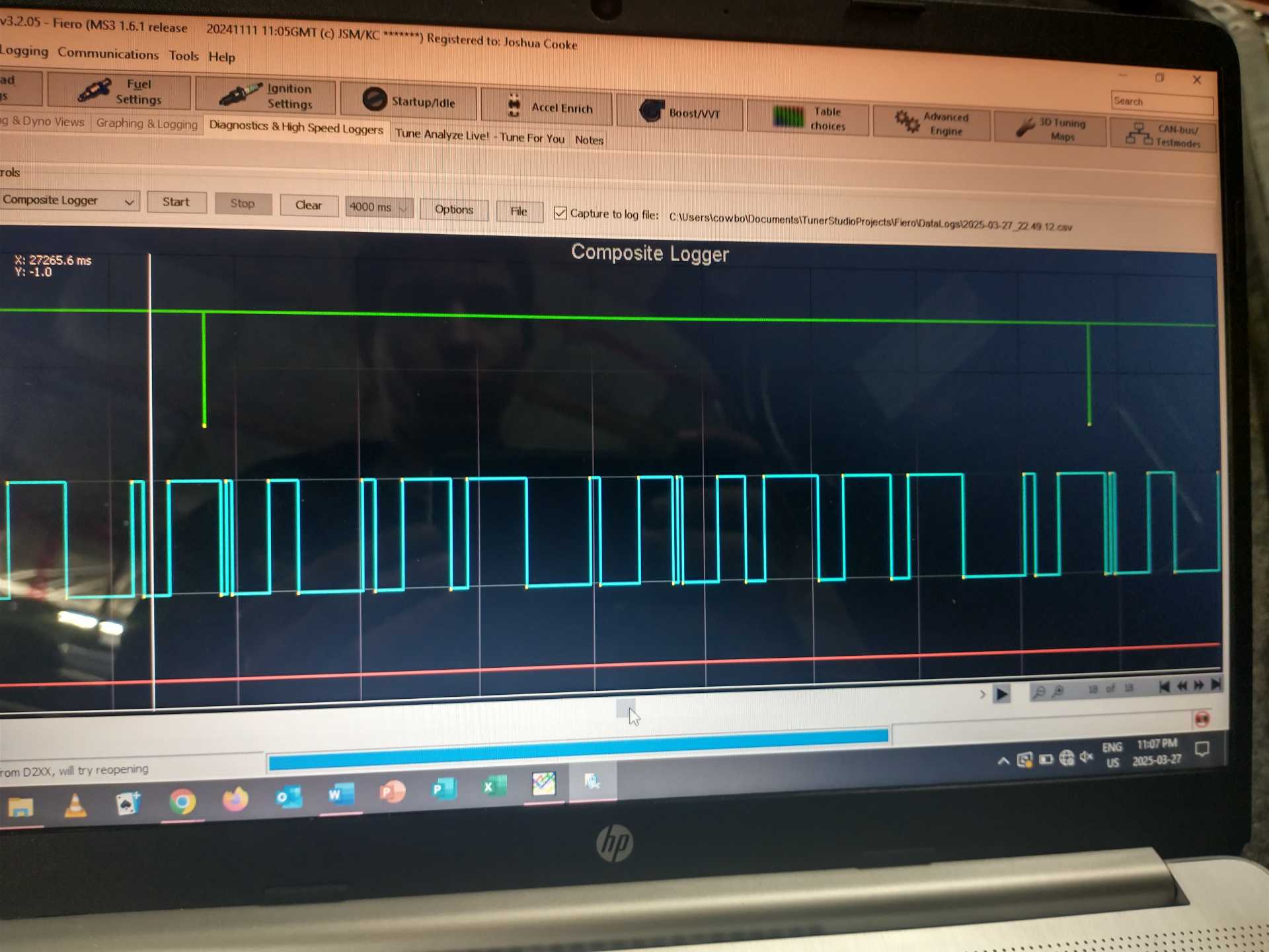
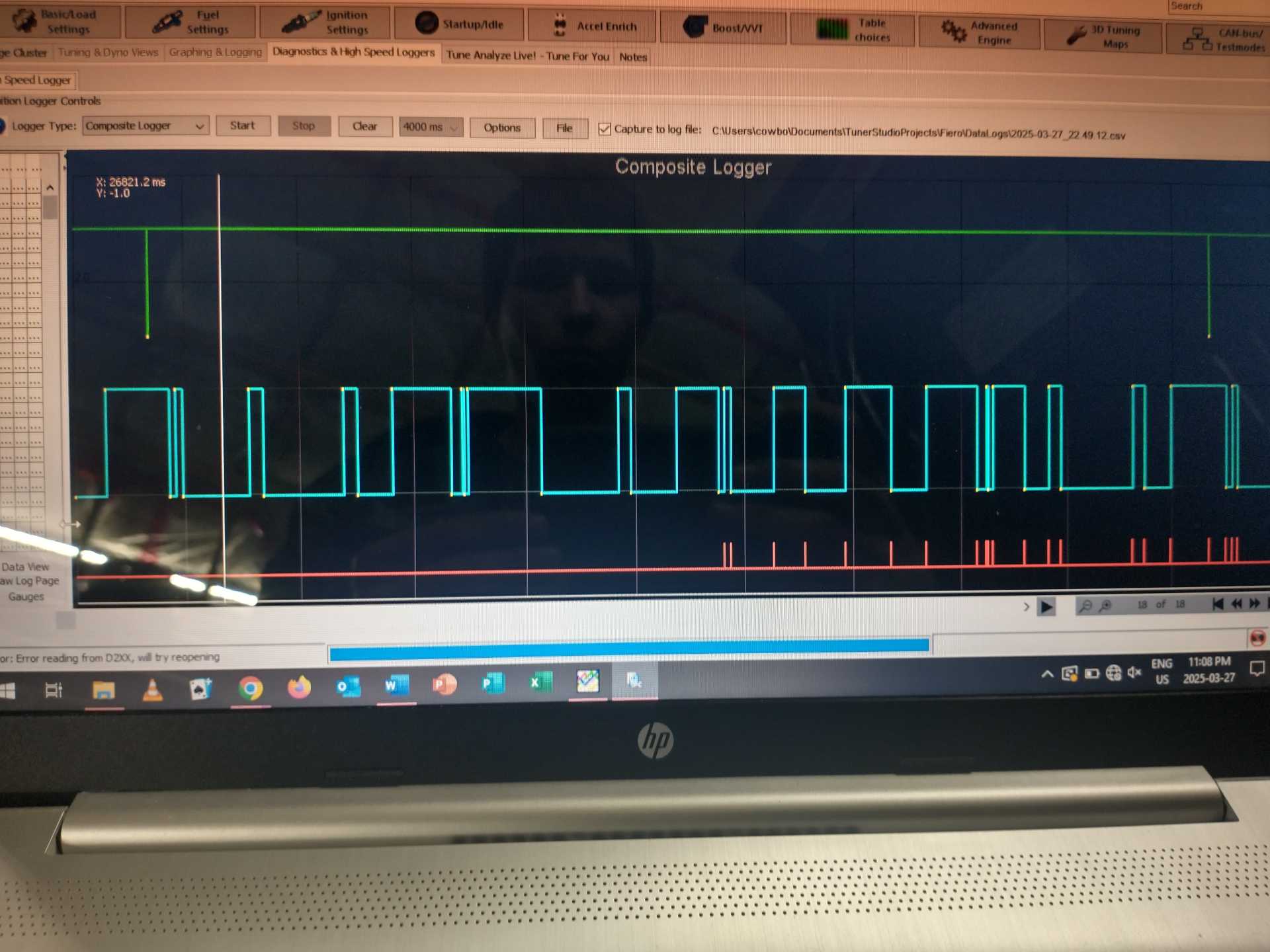
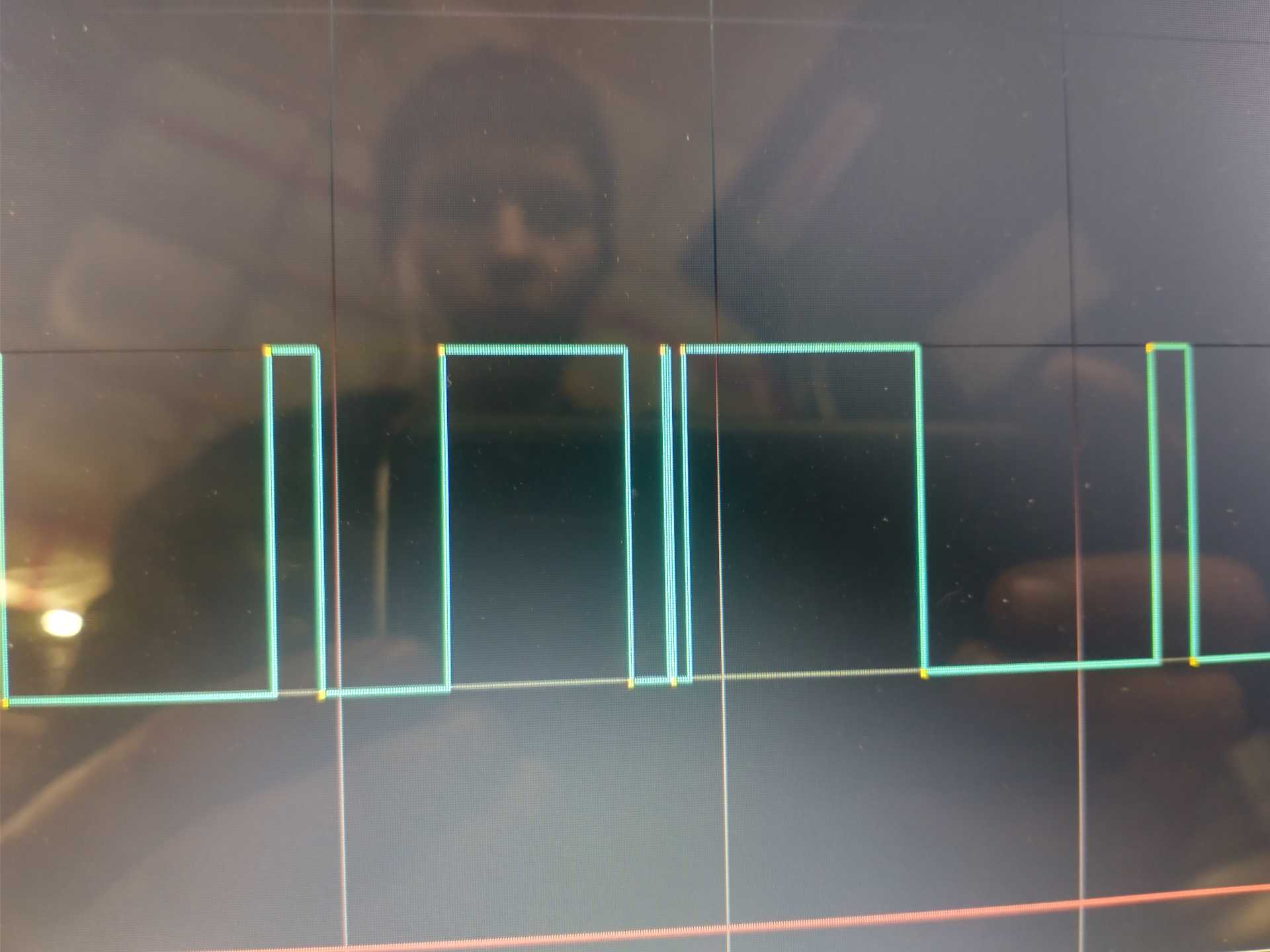
Ok, so got it running, haven't checked that cylinders compression yet, I'm having some loss of sync, in the composite logger, the teeth do not have very similar spacing, although sync is kept up to 2000 rpm, at 2000 it stumbles and looses sync, attached are some pictures, I'll upload the composite log once I'm back home for anyone interested, it seems to take a specific 2 teeth, and blend them into 2 long and 1 short in the middle.
"Good" area (no sync loss, but tooth spacing looks uneven: Issue area: Close up of the 2 errant teeth:
Thoughts? I took out the VR crank sensor, it was clean, no metal particles on it.
Originally posted by 1985 Fiero GT: "Good" area (no sync loss, but tooth spacing looks uneven:
Uneven is not good.
How unstable is the ignition timing when you look at it with a strobe lamp compared to stock? Timing instability isn't so important for now when driving around calmly, but you'll want it stable when you're running at WOT.
If you are using the onboard VR conditioner of the MS, then there are trimpots you can try adjusting to get a better signal.
If that doesn't work, you may need some other VR conditioning solution...
When it is acting normal, timing is dead solid I'm pretty sure (I timed it a while back, don't fully remember, but I'm pretty sure it was dead solid), stock actually wandered a few degrees for me, I haven't used the timing light when it is malfunctioning, because I don't have enough hands, and I don't really want to hold it in a lost sync area for very long, it is very predictable at the point that it acts up though
I was asking about the timing stability in the "Good" area, because in your picture, even the "Good" area appears bad.
Yeah I don't know for certain how solid it was, I would have noticed if it was worse than original, but I don't know how "perfect" it was, but yeah, it probably wasn't great from how bad that data looks haha!
Hmm, I am still using the original ignition control module, just have the 5v bypass signal on all the time so ignition timing is fully megasquirt controlled, in theory I could run the crank VR signal to the pickup coil connector on the ICM, then run the ECM tach signal to the crank signal in. Perhaps that wouldn't be good because I'd still have to run the VR wire a couple feet, and I'm sure running it to the distributor would add a lot of noise. I see 4 pin hei modules are real cheap, so I might do that, just have to find the wiring connectors (are they both the same as is on the pickup coil in the Fiero distributor? If so I have at least one of those)
I got my intake and valve cover back from being powder coated, Chevy Torch Red, satin silver, and clear over all that, they look beautiful! Cost was about $500cad, best price I could find.
This looks amazing!
I noticed you have what looks like an intercooler in one of the pictures above, but it's tucked way out of the way where the cruise control servo and canister would have been. Do you have a picture of that? I was trying to see how you installed it down there and what it looks like.
Originally posted by 82-T/A [At Work]: This looks amazing!
I noticed you have what looks like an intercooler in one of the pictures above, but it's tucked way out of the way where the cruise control servo and canister would have been. Do you have a picture of that? I was trying to see how you installed it down there and what it looks like.
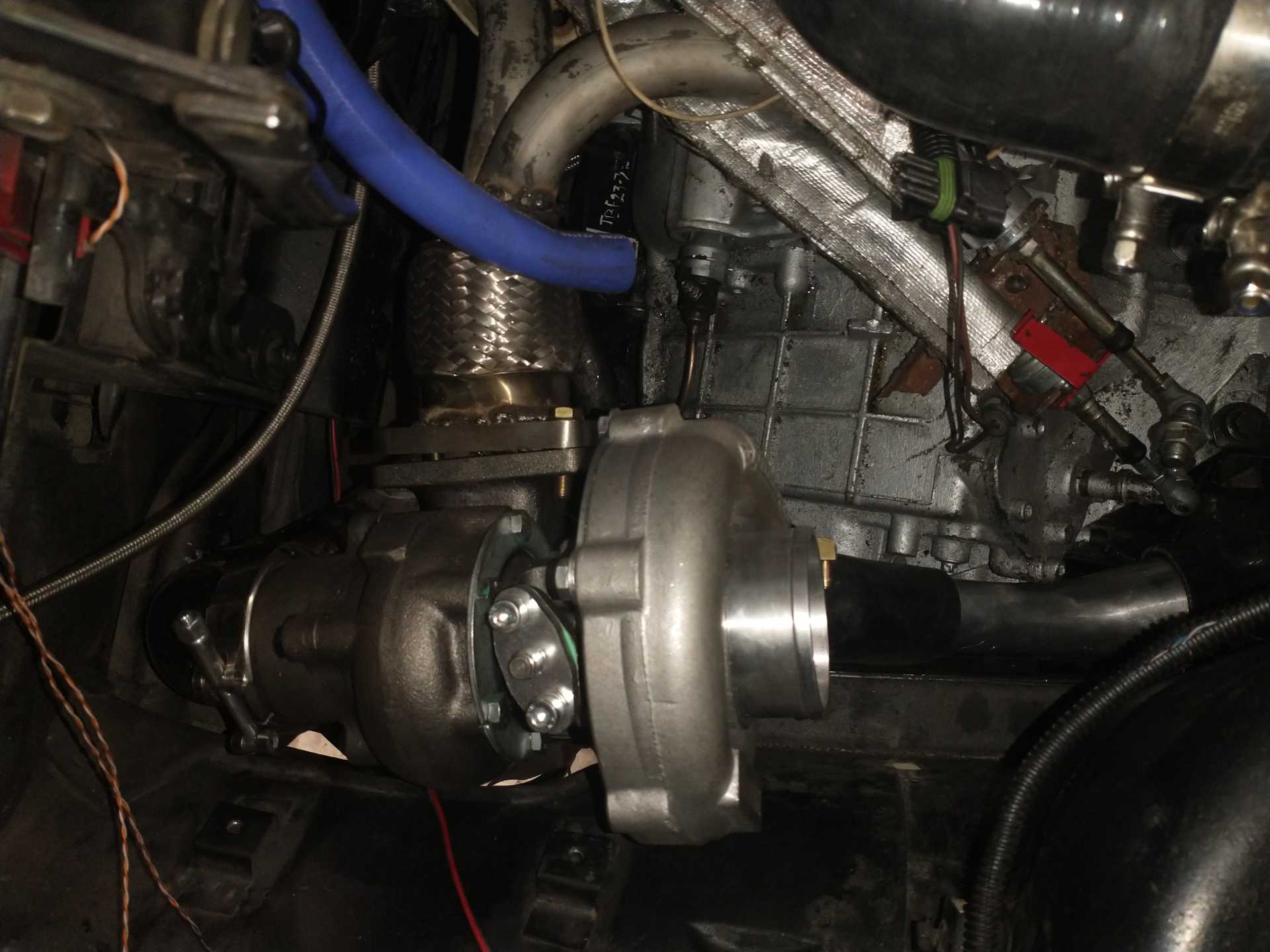
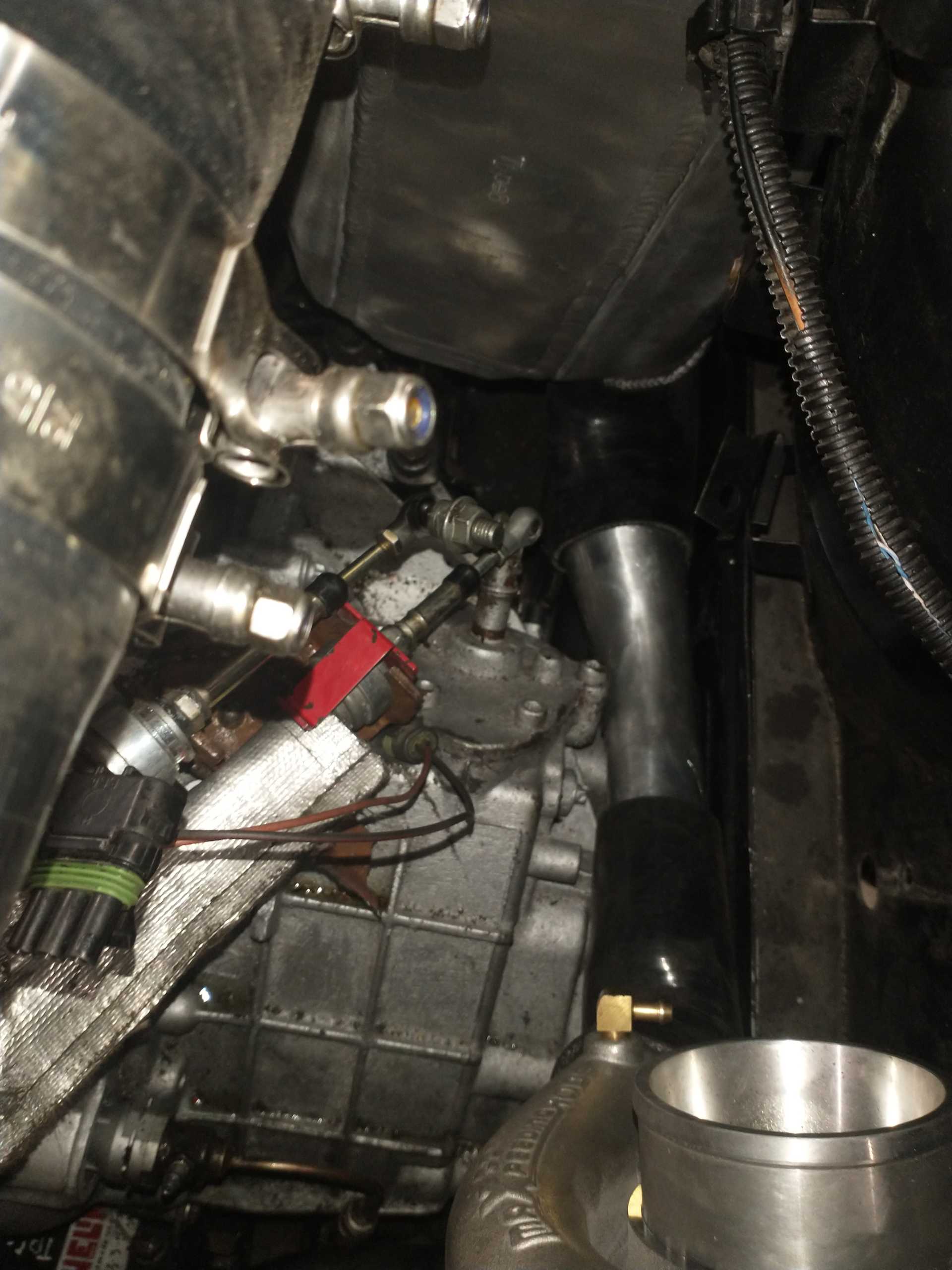
Yup, it did look amazing, one of the bolt locations must have had a defect because it split real bad there, all other bolts were fine, so it's getting sent back (don't have to pay though), the pictures you see are the pictures I have, it's a through io silicone intake intercooler, the in side is at the bottom, there will be a 90*coming out the turbo, then a 45* coming back then down (over the lump my transmission has there), then a 135*to bring it up into the intercooler, it'll clear the CV boot by an inch or 2, then out of the Intercooler, it goes forwards, then 2 45*s to the throttle body. The intake side is not finalized yet, so nothing is precise, I got the exhaust side done last night, and ran the car up to temp (muffled) while working on the sync loss issue, I will say that turbo sounds cool just free spinning exhaust only at 2000 rpm haha, I have a decent exhaust leak at the v band (nicked it with the angle grinder haha), and a few small leaks in my welds that I'll fix, all in all not nearly as bad as I expected haha. I have a short flex pipe between the turbo and the y pipe, and at the bottom of the downpipe (to add flexibility to get positioning perfect, my fabricating skills are nowhere near good enough to just punch something out right the first time haha). I'll remove all the exhaust stuff, put a new v band flange on, fix my weld pinholes, port the wastegate, then wrap the y pipe and downpipe, reinstall, and then work on the intake setup haha.
Oh and as for turbo support, I want to add something but I'm not sure if it's necessary, the exhaust side is being supported by the downpipe and the springs down there, on the intake side, the wastegate actuator bracket is sitting on/in that channel on the frame (passenger side has a heater hose running in it, drivers side is basically just a U shaped shelf that it's sitting on), will I need anything else or should that be good (vertical weight supported by downpipe and wastegate bracket, side to side forces will be held by the flex pipe in the y pipe, front to back should be supported by the downpipe and intake tubing)
Hmm, I am still using the original ignition control module, just have the 5v bypass signal on all the time so ignition timing is fully megasquirt controlled, in theory I could run the crank VR signal to the pickup coil connector on the ICM, then run the ECM tach signal to the crank signal in. Perhaps that wouldn't be good because I'd still have to run the VR wire a couple feet, and I'm sure running it to the distributor would add a lot of noise. I see 4 pin hei modules are real cheap, so I might do that, just have to find the wiring connectors (are they both the same as is on the pickup coil in the Fiero distributor? If so I have at least one of those)
Yeah I'm kindof liking the idea of running the crank sensor to the distributor ICM, then reading the ECM tach output out of that, using the ICM to convert from the analog VR signal to digital for the ECM. Any thoughts on that? Will it be counter productive to run the shielded cable the 2 feet to the distributor, will the distributor itself add a bunch of noise to the signal, or should that "work" fine. I can't test anything for a little while, as the intake is getting recoated, and I'm starting my seasonal job Monday, so now it's the time to order other parts (4 pin hei module) if it's a bad idea to use the one in my distributor already.
Yup, it did look amazing, one of the bolt locations must have had a defect because it split real bad there, all other bolts were fine, so it's getting sent back (don't have to pay though), the pictures you see are the pictures I have, it's a through io silicone intake intercooler, the in side is at the bottom, there will be a 90*coming out the turbo, then a 45* coming back then down (over the lump my transmission has there), then a 135*to bring it up into the intercooler, it'll clear the CV boot by an inch or 2, then out of the Intercooler, it goes forwards, then 2 45*s to the throttle body. The intake side is not finalized yet, so nothing is precise, I got the exhaust side done last night, and ran the car up to temp (muffled) while working on the sync loss issue, I will say that turbo sounds cool just free spinning exhaust only at 2000 rpm haha, I have a decent exhaust leak at the v band (nicked it with the angle grinder haha), and a few small leaks in my welds that I'll fix, all in all not nearly as bad as I expected haha. I have a short flex pipe between the turbo and the y pipe, and at the bottom of the downpipe (to add flexibility to get positioning perfect, my fabricating skills are nowhere near good enough to just punch something out right the first time haha). I'll remove all the exhaust stuff, put a new v band flange on, fix my weld pinholes, port the wastegate, then wrap the y pipe and downpipe, reinstall, and then work on the intake setup haha.
Oh and as for turbo support, I want to add something but I'm not sure if it's necessary, the exhaust side is being supported by the downpipe and the springs down there, on the intake side, the wastegate actuator bracket is sitting on/in that channel on the frame (passenger side has a heater hose running in it, drivers side is basically just a U shaped shelf that it's sitting on), will I need anything else or should that be good (vertical weight supported by downpipe and wastegate bracket, side to side forces will be held by the flex pipe in the y pipe, front to back should be supported by the downpipe and intake tubing)
Will the intercooler be fixed to the spaceframe or will it move with the engine?
To check for pinholes, I have filled my exhaust pipes with water. Water dripped out of any pinholes. To block the exhaust pipes (and hence allow filling with water) in an easy manner, I used aluminium duct tape.
quote
Originally posted by 1985 Fiero GT: Yeah I'm kindof liking the idea of running the crank sensor to the distributor ICM, then reading the ECM tach output out of that, using the ICM to convert from the analog VR signal to digital for the ECM. Any thoughts on that? Will it be counter productive to run the shielded cable the 2 feet to the distributor, will the distributor itself add a bunch of noise to the signal, or should that "work" fine. I can't test anything for a little while, as the intake is getting recoated, and I'm starting my seasonal job Monday, so now it's the time to order other parts (4 pin hei module) if it's a bad idea to use the one in my distributor already.
Noise might be an issue, but it's hard to say without trying it out.
Normally the 5V electronic spark timing bypass will be on during normal operation, but if it ever goes out, your 8-pin module will fire the ignition coil directly according to the 7X wheel. This would likely give unacceptable results with 7 sparks per engine cycle...
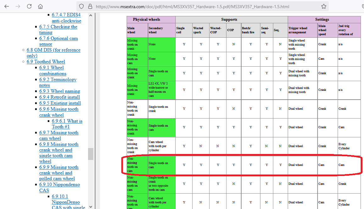
If you want to skip the trouble of properly conditioning the 7X signal, then I think I would try running off the 6-tooth distributor pickup and the stock HEI module, and using the 3400 cam sensor for full sequential. This of course does not give you the accuracy of a crank sensor, as the distributor is subject to play in the timing chain and crossed gears.
I think I would try "Dual wheel" with "Non-missing tooth on cam" (the distributor's reference pulses) and "Single tooth on cam" (the 3400 cam sensor).
[This message has been edited by pmbrunelle (edited 03-31-2025).]
Noise might be an issue, but it's hard to say without trying it out.
Normally the 5V electronic spark timing bypass will be on during normal operation, but if it ever goes out, your 8-pin module will fire the ignition coil directly according to the 7X wheel. This would likely give unacceptable results with 7 sparks per engine cycle...
If you want to skip the trouble of properly conditioning the 7X signal, then I think I would try running off the 6-tooth distributor pickup and the stock HEI module, and using the 3400 cam sensor for full sequential. This of course does not give you the accuracy of a crank sensor, as the distributor is subject to play in the timing chain and crossed gears.
I think I would try "Dual wheel" with "Non-missing tooth on cam" (the distributor's reference pulses) and "Single tooth on cam" (the 3400 cam sensor).
yeah, i figured if anything happened to the ecm to stop sending the bypass signal then its probably not going to be running at all.
Interesting, I didn't realize it was so flexible haha, I do want to get the crank sensor working though, I'll test it using the distributor icm, if it works that way, I'll probably leave it like that, if it's better but still not perfect (noise) I'll probably get a 4 pin icm and mount it real close, if it's no better, I'll use my distributor pickup and call it a day.
[This message has been edited by 1985 Fiero GT (edited 03-31-2025).]
Will the intercooler be fixed to the spaceframe or will it move with the engine?
To check for pinholes, I have filled my exhaust pipes with water. Water dripped out of any pinholes. To block the exhaust pipes (and hence allow filling with water) in an easy manner, I used aluminium duct tape.
I haven't gotten to the intake other than basic planning, it will be jammed up on 2 sides by the engine bay, so probably i'll fasten it to the frame, the path to the throttle body will be 4 silicone sections, a couple feet long, and have two 45* in it, so that should absorb any powertrain movement without tugging the intercooler, and provide more support for the turbo.
I like that idea, my initial test was just the engine running, and it is honestly less leaky than my stock fiero when i got it (manifold cracked in two) i felt one minor leak in the y pipe, and the vband is leaking like it isnt even there (nicked it without thinking with the angle grinder, then attempted to grind it flat and failed miserably haha). the way I've always found leaks is to put rubber gloves over 3 exhaust pipes, stick a shop vac (blowing) in the 4th, and spray everything down with soapy water. when i take everything off again, i think ill plug the ends and use an air compressor (dont have a shop vac anymore) and soapy water, but i'll remember that idea to fill them up if that doesnt work, i like that haha.
You might be triggering on the wrong edge (falling vs rising); that might be making things unstable.
yeah, I tried playing around with all the different options, ignition input capture rising and falling edge, flip polarity on high res tach/cam, I couldn't even get it to start any other way than what I have (falling edge and normal), and come to think of it, i think it was fully messed up when cranking as well (registering to many teeth) as my tach was reading 1000 when cranking (not something i was specifically looking at, just realized after the fact), and it was harder to start this time than the last time (which come to think of it could have been from getting flooded due to the ecm thinking it was turning faster than it really was). nothing i did made anything better haha, I think once it revved to 3500 rpm, just once, all the rest of the night, it stumbled at 2000, so i guess it has sync (poorly, but useable) between like 750 rpm and 2000, above and below, it is messed up haha.
Well, major sidetrack, I'm getting t tops! It'll be all the parts from a rear end damaged 88 cjb, probably not in the best condition, but looks ok, anyhow I won't know until mid May, when I'll be getting them, but I've had water leaks and have major wind noise from my sunroof already, so it can't get worse! Anyone have a digital copy of the t top install manual, I've tried looking online but it seems all the links are old and dead.
I’m working on something kind of similar, no turbo but I’m doing a 3100 F23 swap. I want to drive it as soon as possible so I won’t be doing too much else, not yet anyway.
I like your approach of using plastiguage, I think it can get over complicated otherwise and become intimidating. I’ll have to do the 3100 rod caps/main bearings in the next couple years, but I think they have enough life left in them.
What state are you in? If you are less than 500 miles away we should meet up.
Well, major sidetrack, I'm getting t tops! It'll be all the parts from a rear end damaged 88 cjb, probably not in the best condition, but looks ok, anyhow I won't know until mid May, when I'll be getting them, but I've had water leaks and have major wind noise from my sunroof already, so it can't get worse! Anyone have a digital copy of the t top install manual, I've tried looking online but it seems all the links are old and dead.