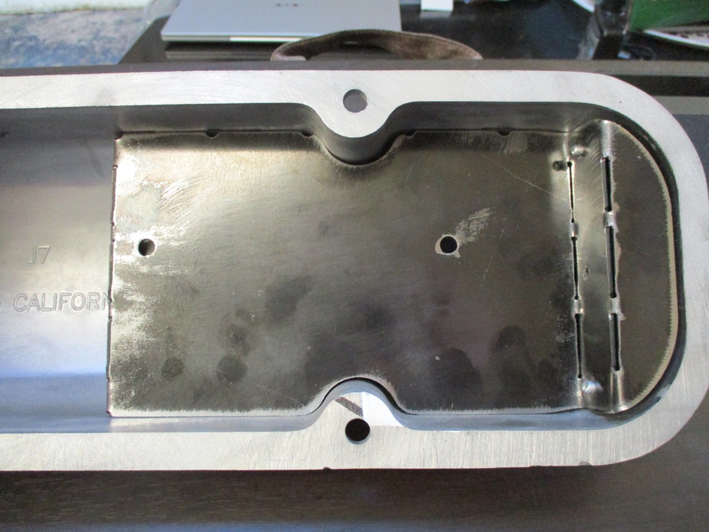
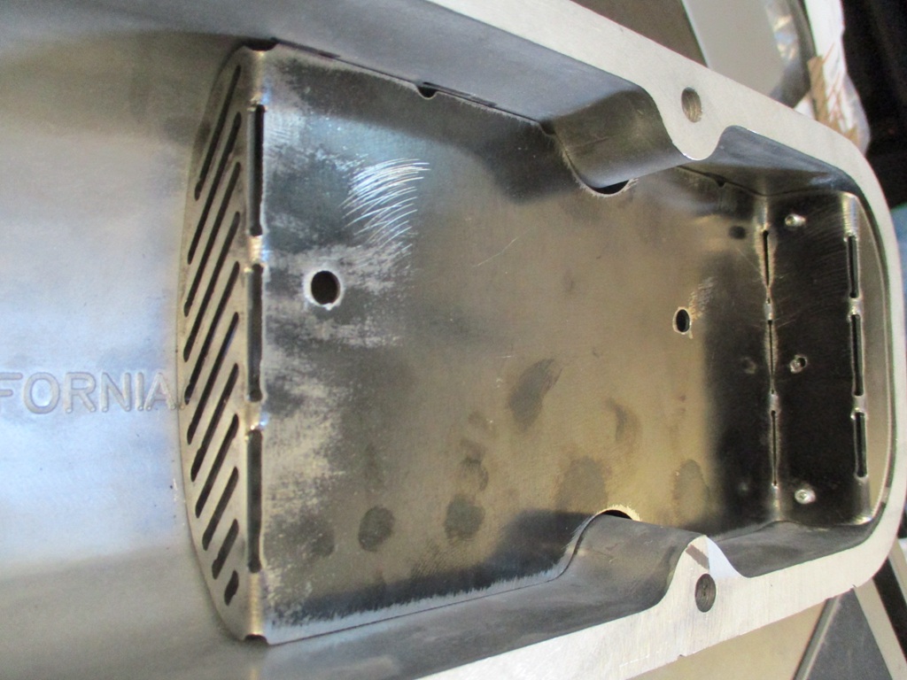
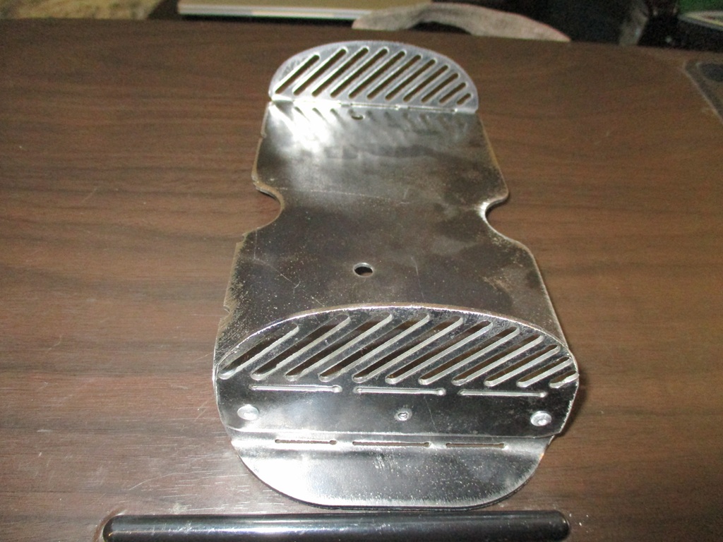
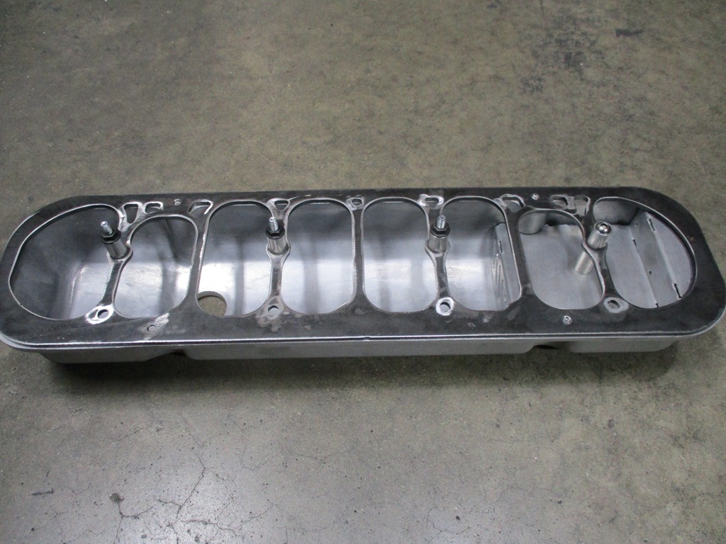
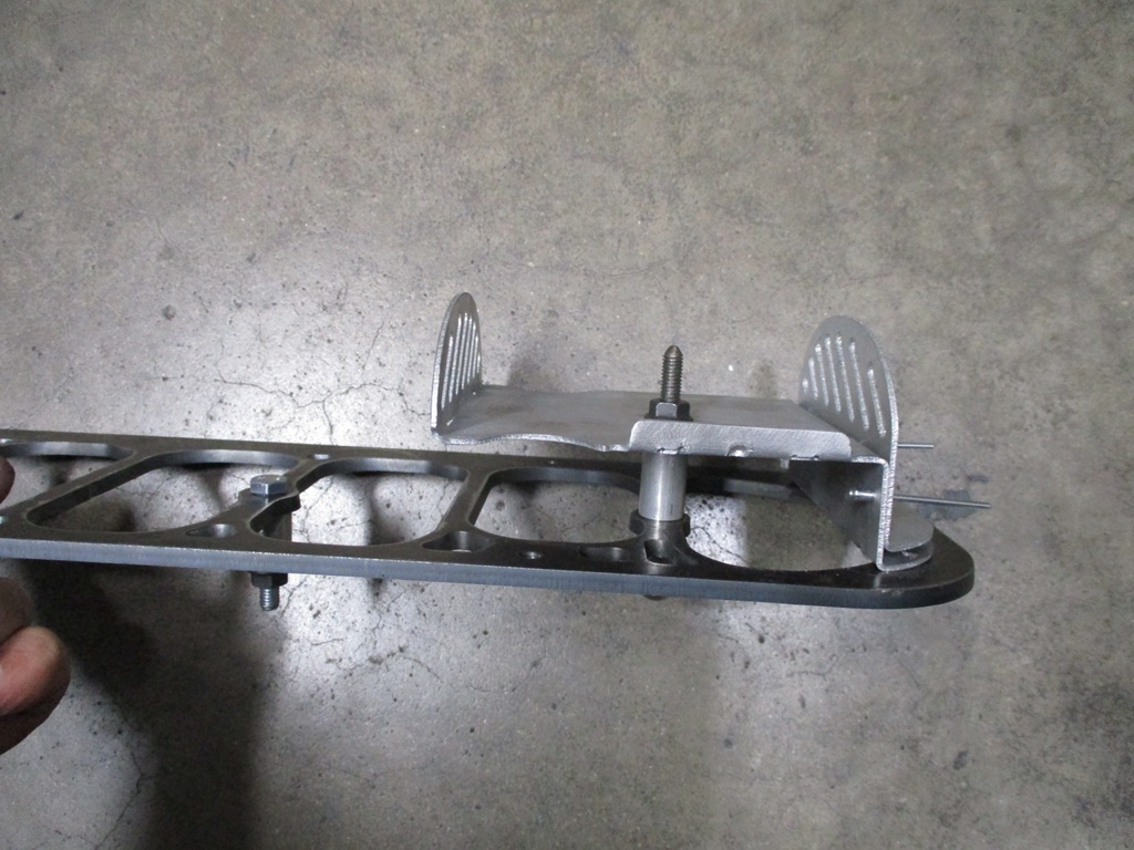
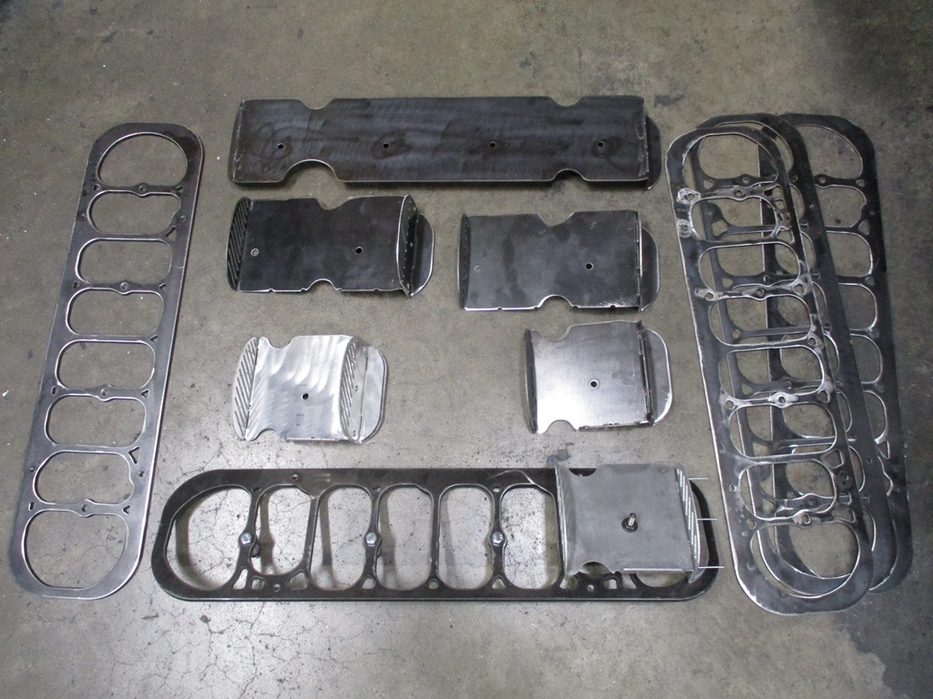
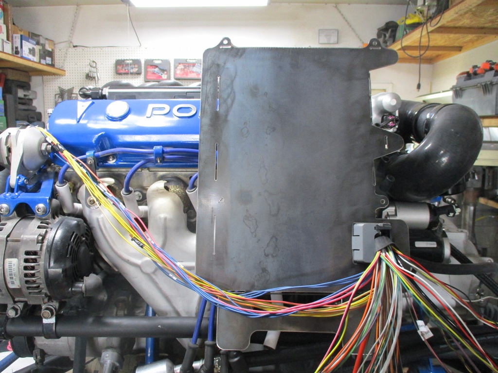
Continuing to refine the valve cover baffle... Decided it didn't really need to be the full length, so left it with only using 2 of the valve cover holes and started working on the end caps. I still need to shift the openings around the valve cover bosses and tighten them up some.
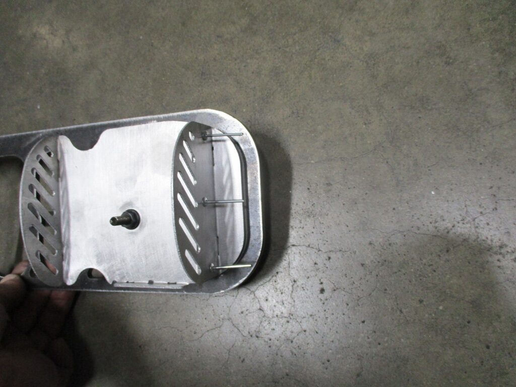
When the valve cover is installed, the 1/8" wide slots will be vertical.
The plate on the exit side still needs some work. It was shaped to fit, so the 1/8" spacing from the end of the slots to the end of the plate were lost. The next iteration will also start having some bent up tabs along the bottom to help hold the baffle material in place when the valve cover is lifted off.
Once I get something I am happy with, I might try cutting it out in 16ga aluminum, as it would be lighter.
Looks nice. What PC gun did you use? I have the harbor freight one and did some 88 caliper bridges I used the HF red and they turned out great. They cleaned off so much better than painted. I had an old toaster oven. But it's too small for valve covers. What did you use for an oven?
Looks nice. What PC gun did you use? I have the harbor freight one and did some 88 caliper bridges I used the HF red and they turned out great. They cleaned off so much better than painted. I had an old toaster oven. But it's too small for valve covers. What did you use for an oven?
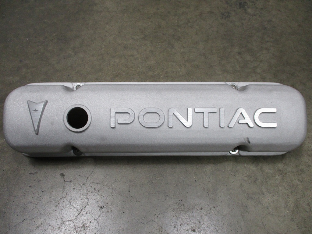
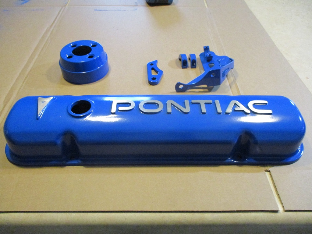
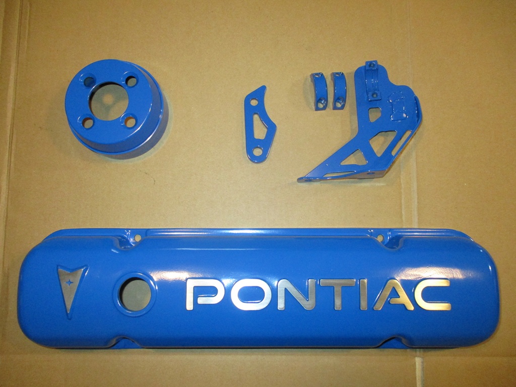
I picked up an Eastwood PCS-250 Dual Voltage powder coat gun last year. I used the higher 25K volt setting. Before filling the powder, I screened it through some paint filters. Powder was from Prismatic Powders. 400 degree cure temp for 12 minutes. Used the kitchen oven.
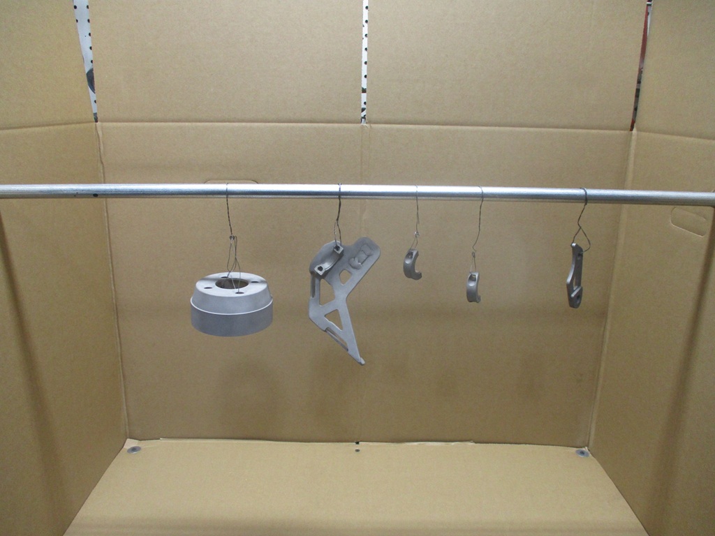
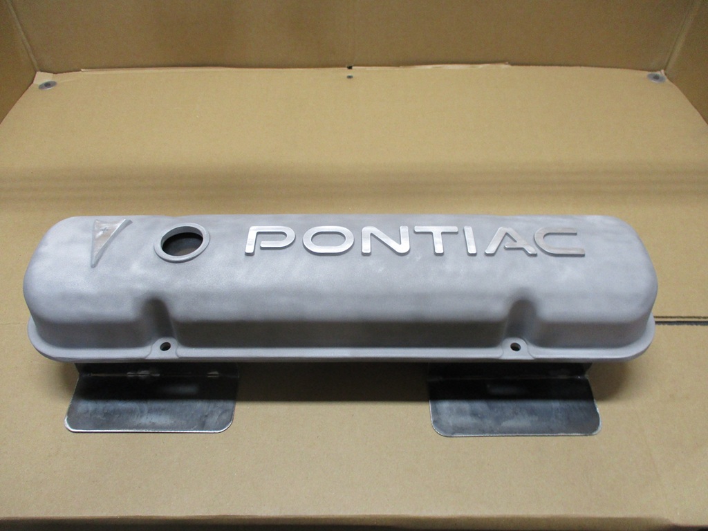
Here are all the steps to prepare and finish the valve covers. Cleaned them with brake clean and let dry for a day. Preheated the oven at 450 degrees for 2 hrs, while cleaning the racks from any oils/grease. Baked valve covers in the oven at 450 degrees for 30 minutes to bring any contaminents to the surface - I wanted this to be hotter and longer than the powder coating cure. Sand blasted the covers. Cleaned with brake clean again. Used 220 grit sandpaper with a 2" x 2" x 10" aluminum block and smoothed out the letters and emblem. Applied the powder across the entire valve cover. Wrapped tape around the block with sticky side out. Placed the block over the letters and emblems a few times to remove about 80% of the powder. Wiped the rest off the letters with my fingers. Baked & cured. Used the same block with 320 grit sand paper to further smooth out the letters and emblem.
[This message has been edited by fieroguru (edited 04-01-2025).]
how did you filter the powder through the paint filters? My initial thought is that the screen on a paint filter would be too small to easily let powder go through it. So if you filled it up part way with powder, then held the filter over a bowl and "shook" it (lightly, of course), very little would get through before the larger particles would clog it up?
The double clean process is something I suspect a lot of shops don't do, which is a shame because the purpose makes sense. One of the places Mike used to use for powder coating made it clear they weren't going to do any prep work, they expected the part to be ready to spray-and-bake. He no longer goes there. lol
Originally posted by Trinten: how did you filter the powder through the paint filters? My initial thought is that the screen on a paint filter would be too small to easily let powder go through it. So if you filled it up part way with powder, then held the filter over a bowl and "shook" it (lightly, of course), very little would get through before the larger particles would clog it up?
I just scooped the powder into the filter with a spoon and then tapped the side of the filter with the spoon and the powder passed through the filter - slowly. The powder is very fine, so nearly all of it passed though.
quote
Originally posted by Trinten: The double clean process is something I suspect a lot of shops don't do, which is a shame because the purpose makes sense. One of the places Mike used to use for powder coating made it clear they weren't going to do any prep work, they expected the part to be ready to spray-and-bake. He no longer goes there. lol
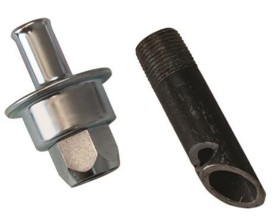
I tried my best to keep the valve cover clean while doing all the test fits, but when I tapped the ends for the PCV hose barbs, that required oil, whch can be absorebed into the pores of the aluminum
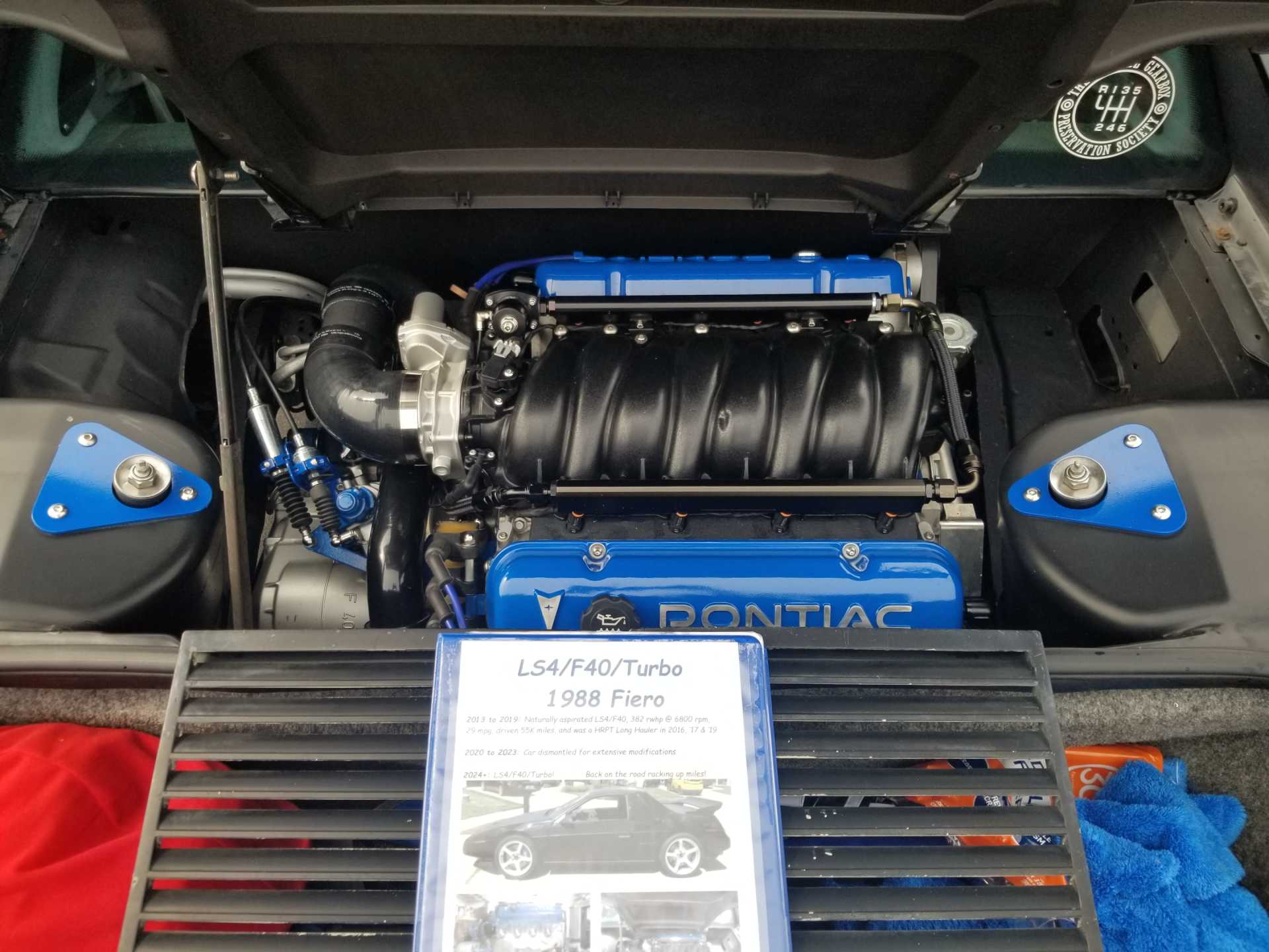
This is the 4th set of power coated valve covers in the last year or so. First was my original oem smoothed set. I had to remove the bondo and used JB weld so the powder would stick. Didn't do any preheat and the JB weld shunk as the powder cured... scrapped set #1. 2nd set was another smoothed set, but had too much porosity, so there ended up being porosity and holes in the coating... scrapped set #2 3rd set is what was on the car the last year. They were OK, but some sanding scratches showed through. Most people wouldn't notice, but I knew they were there and the valve covers were pretty plain.
I wasn't taking any chances with the current set, so I did everything I could to ensure they were defect free, time and $$$ was less important than the end result.
Most would think it is insane the $$$ spent chasing this valve cover obsession (cost of 3 new valve cover sets, billet adapters I didn't use, and the countless hours in each iteration, the current adapter plates, and the PVC/catch can baffles... all to satisfy my quest for a certain look and avoiding the hoses and clutter of catch cans.
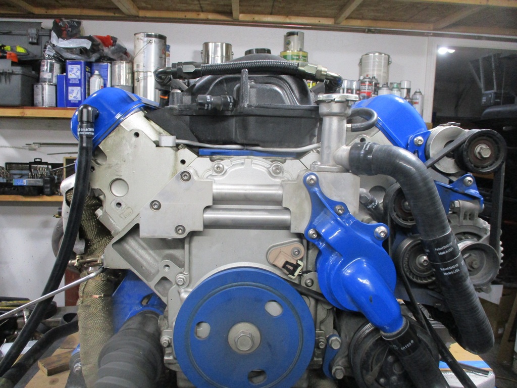
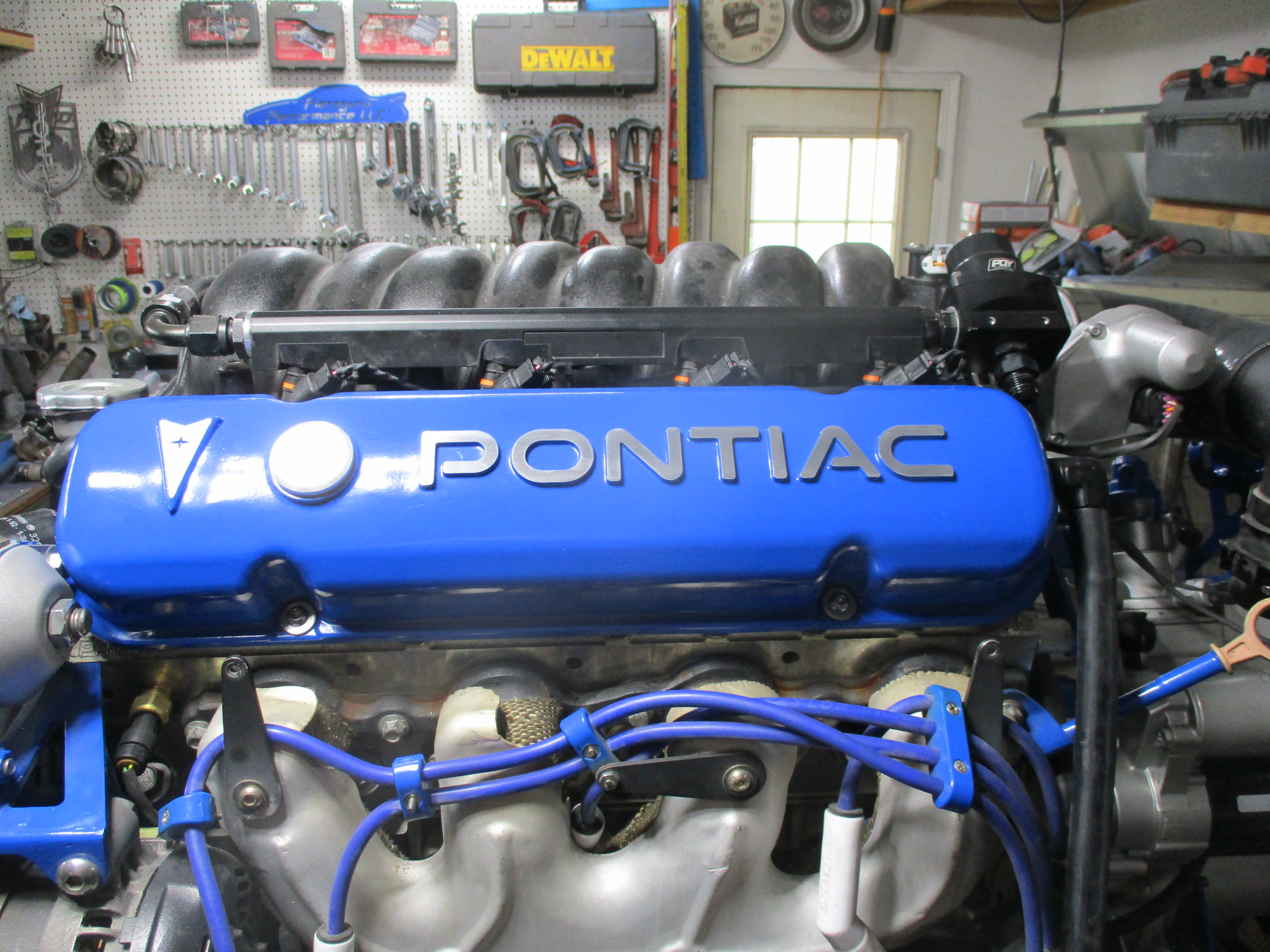
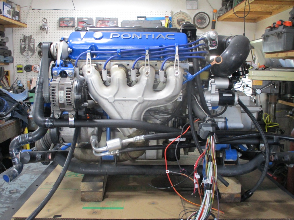
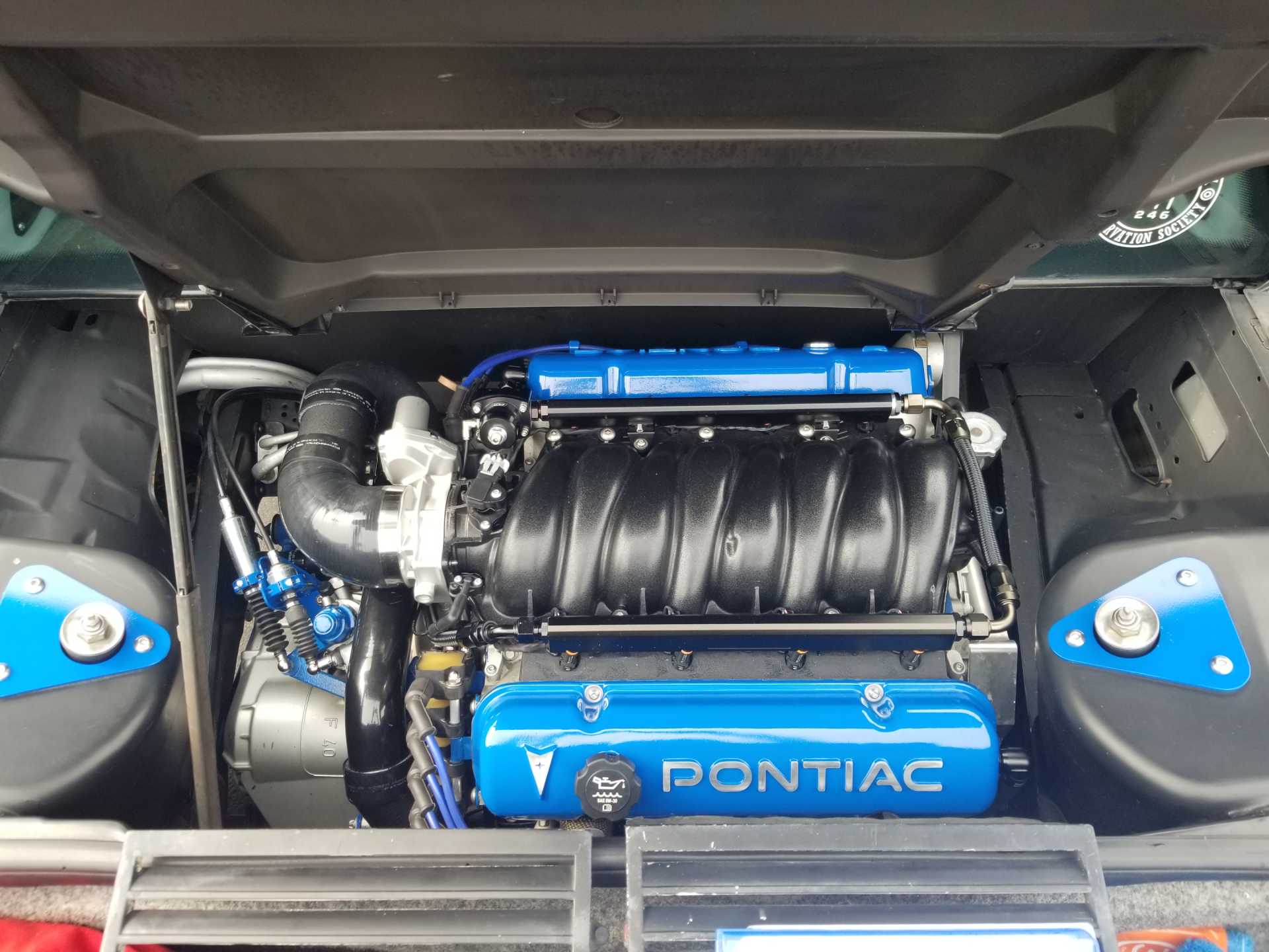
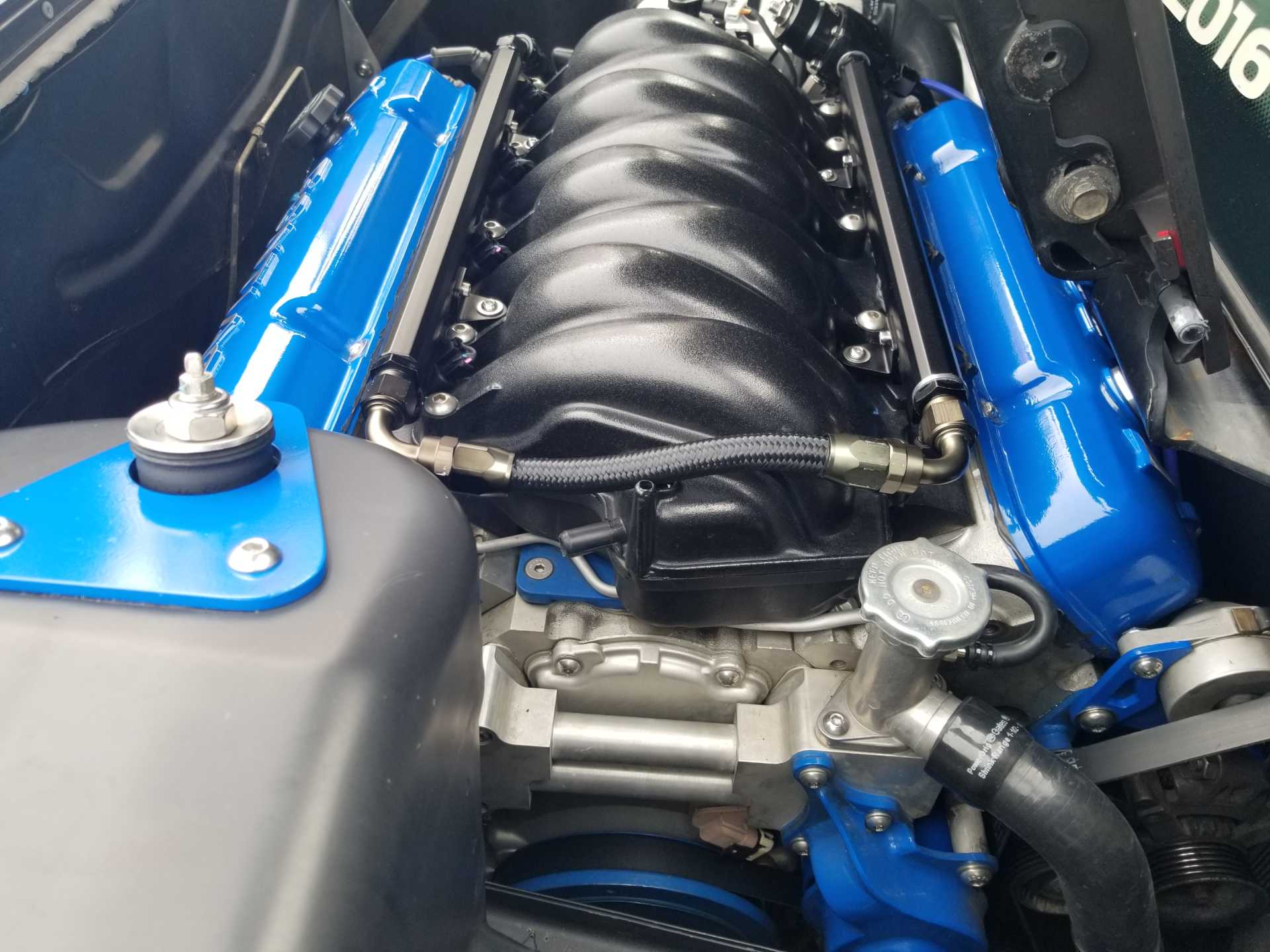
Finished the work on the valve covers. Installed the two PCV hose bibs on the ends of the valve cover, and made filler caps. The front one I made an aluminum plug and an o-ring seal and bolt on the inside that holes if in place. The rear one I modified the LS4 oil fill cap to work with the old style rubber grommet fill point. Once those items were done, installed the adapters, then the stainless brillo pads, then the valve covers for hopefully the last time.
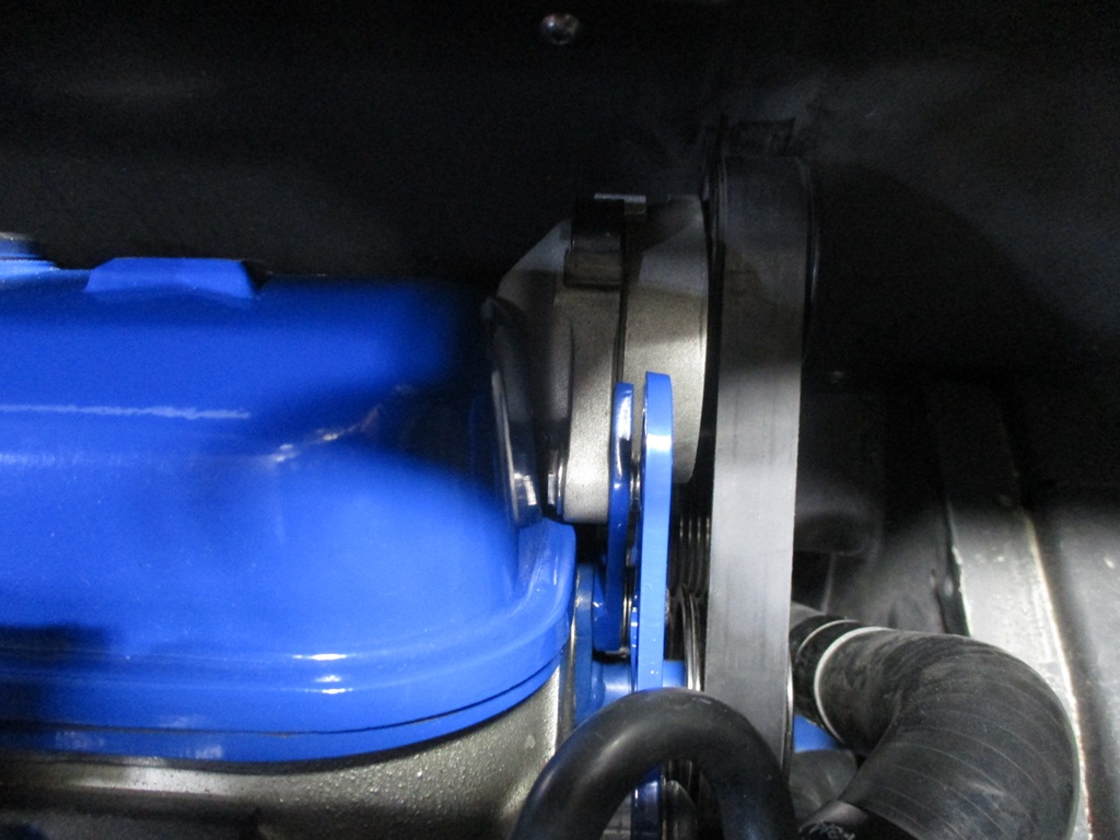
Once the valve covers were done, I could install the new bracket for the tensioner, the water pump with the new pulley, and heat shrink the thermostat hose to the new cross car coolant tube. With the pulley being smaller and the tensioner moving up, the original belt still works.
Started looming the harness from the back of the engine. Continued to loom the harness around the bellhousing, picked up all the wires for rear coils, the transmission and intake manifold. The harness on the intake was zig zaged between the injectors and the bosses for the hold down bolts to help keep it hidden. Stopped looming the harness over by the starter. Still need to loom the front of the engine, the front coil pack, and then install the mockup for the ecm panel and the firewall pass through.
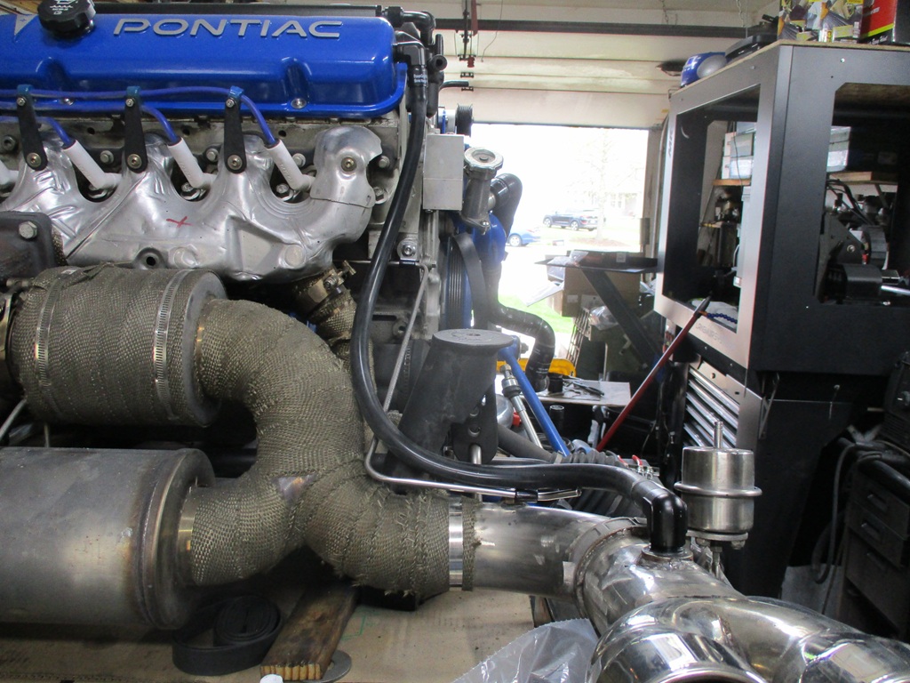
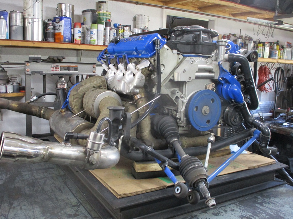
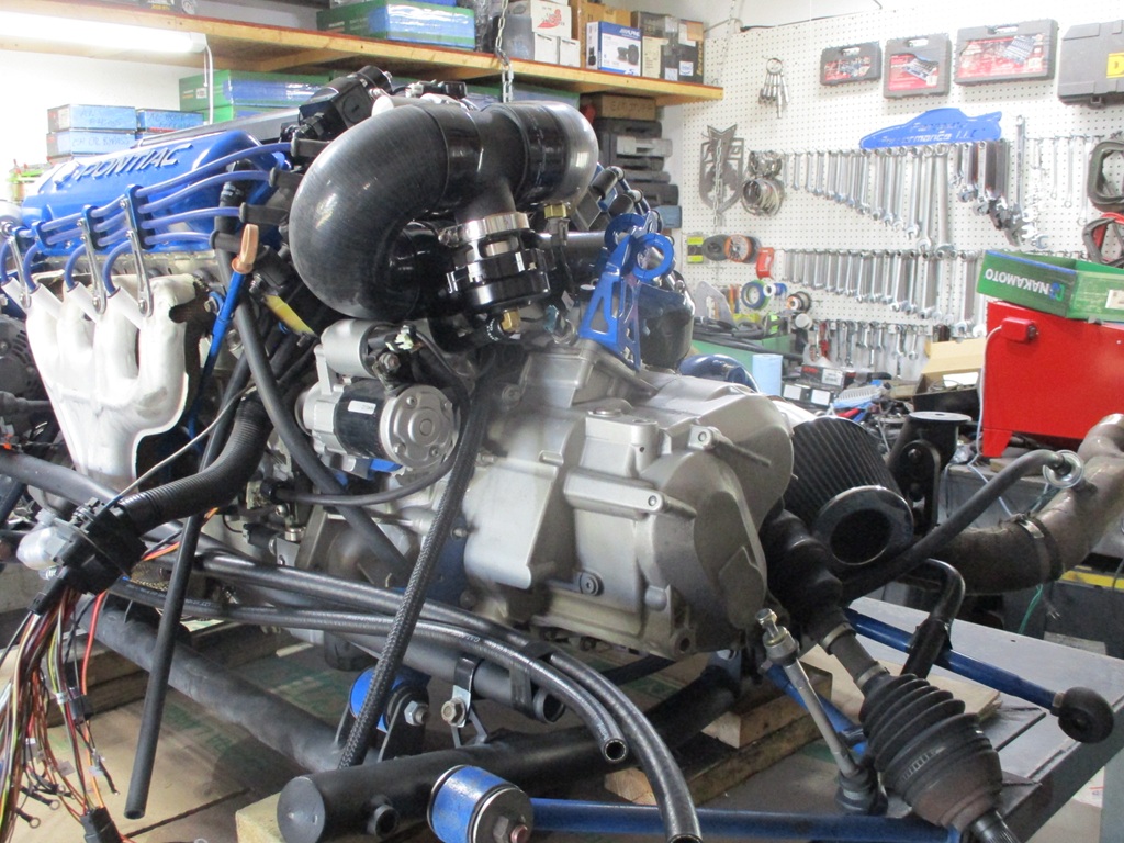
With most of the rear wiring loomed, started playing with rerouting the charge piping and mocking up the TR-8C. It looks like I need cut off both hose barbs off the end and weld in some tight 90s to make the needed room for it to fit. With the hose barbs, there isn't enough room for the 90s that are needed. By welding tight aluminum 90s, I will gain about 3" overall which would work. The other issue with the A/C compressor mounted low, the hardlines coming out of the compressor interfere with the 3.5" thick intercooler with the intercooler flush with the bottom of the cradle. So I picked up a new LS4 A/C hose setup, cut off the hoses, and just kept the compressor end. Crimed on the new hoses, and gentrly pursuaded the hardlines to alter their path. Ended up with 1/4" clearance. I can't finsih the A/C hoses until the engine is in the car. I am also kicking around switching to an A2W intercooler setup with the heat exchanger where I planned to mount the TR-8C. The A2W is supposed to support 1200 hp and the TR-8C is rated for 500 hp. With either solution, I needed to reroute the charge pipe to the front of the engine. So I spend the rest of the day working on rerouting the charge pipe.
The direct route is for the 2.5" pipe to go over the top of the transmission and under the throttle body. To help with this I needed to rotate the compressor housing so the outlet wasn't vertical. That required a 2nd bolt for the clamp plates to be countersunk to clear the oil drain housing, so the compressor housing needed to come off. While it was off, I went ahead and drilled out the compressor housing boost reference boss. With the compressor back on and rotated, I was able to reinstall the air filter. Then spent a fair amount of time adjusting the leg lengths on a couple of 45 silicone hoses to offset the charge pipe so it will clear the coils, the shifter counterweight (reverse if the limiting factor) and the bottom of the thottle body hose. Once the hoses were good, then started trimming the 2 1/2" hardline. With the 2 1/2" pipe on the front side of the throttlebody, this position will work for either intercooler setup.
So to be able to drive the car while I figure out the intercooler solution, uses a 2.5 to 3" reducer, a 3" 180 hose, a 3" hard pipe with blow-off port, and a 3 to 4" 90 degree elbow.
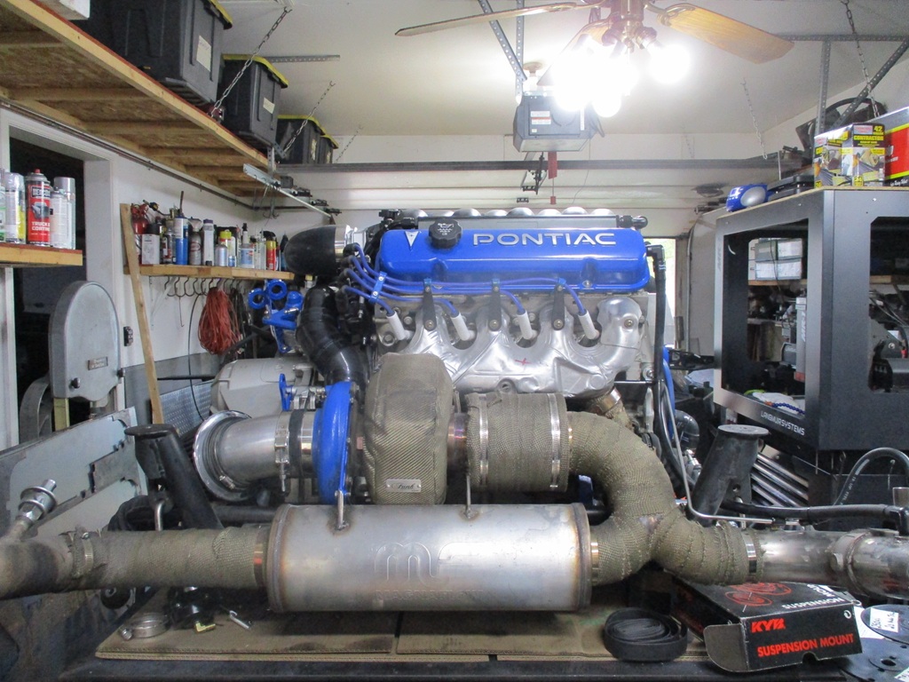
Here are some progress pictures:
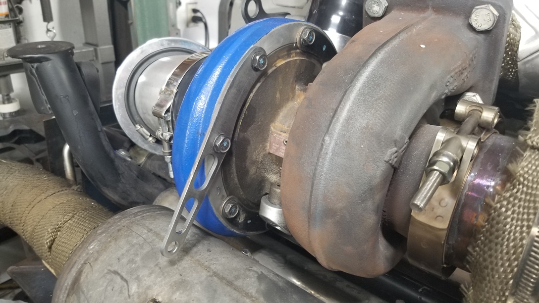
Now, I need to run the poly lines from the compressor, to the mac valve, to the wastegate. Then install the exhaust and rework the support off the compressor housing (with it now rotated, I need to rework this bracket. Then get back to wiring and terminations.
Most would think it is insane the $$$ spent chasing this valve cover obsession (cost of 3 new valve cover sets, billet adapters I didn't use, and the countless hours in each iteration, the current adapter plates, and the PVC/catch can baffles... all to satisfy my quest for a certain look and avoiding the hoses and clutter of catch cans.
Thank you for the details and explanation. And if anyone can appreciate chasing an outcome to get exactly what you want regardless of the time/money/difficulty, it's me.
Only had 1 day this weekend to work on the Fiero. Things that are completed:
Charge pipe from turbo to throttle body. Air temp sensor in charge pipe. Poly boost ref line from intake to fuel pressure regulator and line to the passenger compartment for the gauge. Poly boost ref line from compressor to mac valve. Loomed the rest of the engine side of the harness. Installed the mock up firewall with pass through. Pulled wires through pass through and started to separate them to where they go.
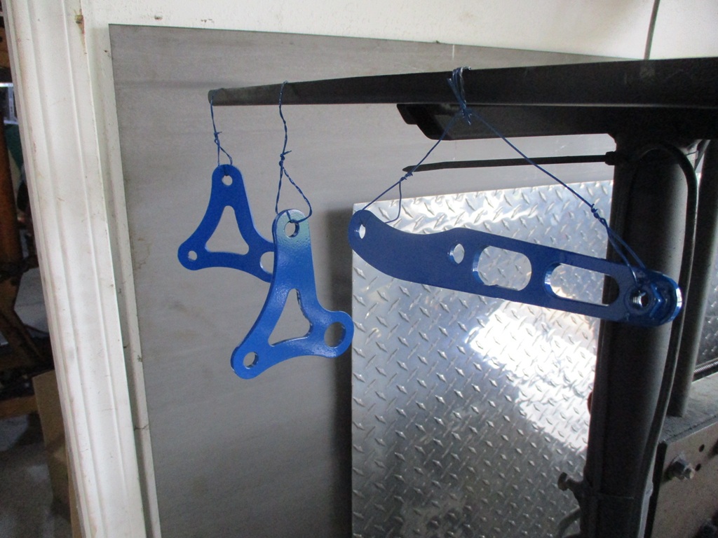
While I was playing in AutoCAD for the wiring, I went ahead and drew up some lifting eyes for the engine and transmission to help with getting it off the table and onto the legs of the cherry picker. I made the engine one first then adapted it to the transission one.
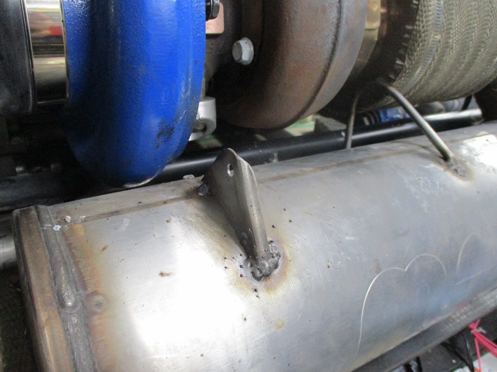
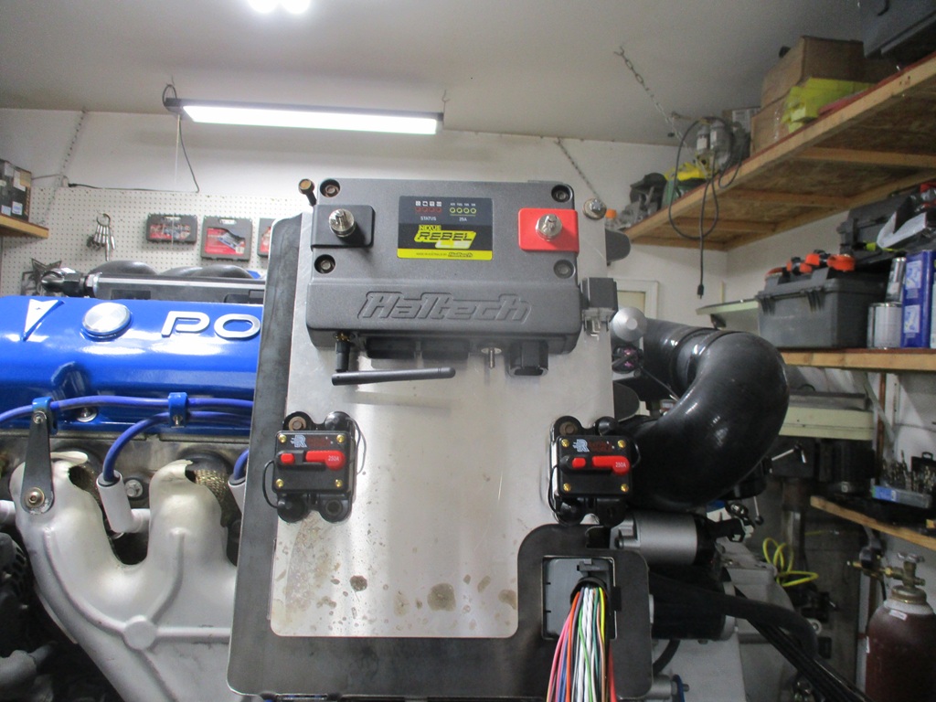
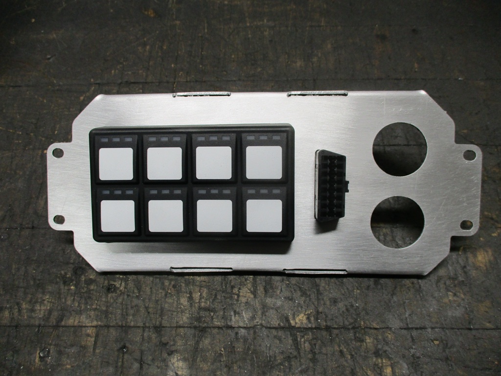
Installed and leveled the exhaust Fabricated a new bracket from the compressor to support the exhaust Fabricated a new bracket from the muffler to the new compressor bracket Fabricated the ECM panel and installed the ECM, A/C Relay, 2 circuit breakers. Route hose for PCV to passenger side exhaust - this is after the boost activated cutout and will work for clean air intake, and vent any crankcase pressure under boost. Fabricate the 1.5 DIN radio panel that will hold the Haltech 4x2 CAN buttons, OBD2 connector, 2 USB charging ports (in 1 housing), and 12V accessory socket. Sandblasted and powdercoated the new lift and ehaust brackets
I am off this coming Thursday and Friday and want to have the drivetrain back in the fiero by the end of next weekend.
Can you elaborate more on your crankcase ventilation setup?
Does the exhaust pipe work better than a road draft tube due to higher velocity?
Generall consensus is the header/exhaust evac is more efficient than the road tube.
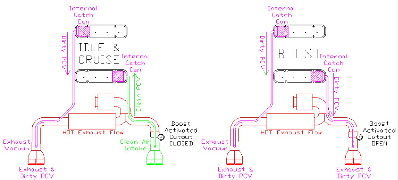
Both valve covers have integraded self draining catch cans with baffles and stainless brillo material to remove the oil from the PCV vapors and to "filter" the clean air coming in. I use air quotes as this filtering process will not be ideal, which I am OK with.
There are 5/8" hoses from each valve cover running to each exhaust tip.
The driver side has one of these before the exhaust tip. This side of the ehaust is always flowing at idle, cruise, WOT, and under boost and the exhaust flow produces a slight vacuum to pull clean air through the engine and out the front valve cover.
The passenger side has a boost activated (actually pre-turbo exhaust back pressure activated so it opens sooner) cutout. This means that at idle and cruise, the cutout is closed, so there is no exhaust flow through this tip. A simple threaded 90 will pull air from inside this tip at idle and cruise to route through the engine.
When the engine is under boost, there will be positive crankcase pressure. Under this condition, both 5/8" hoses will flow dirty PCV vapors to both exhaust tips.
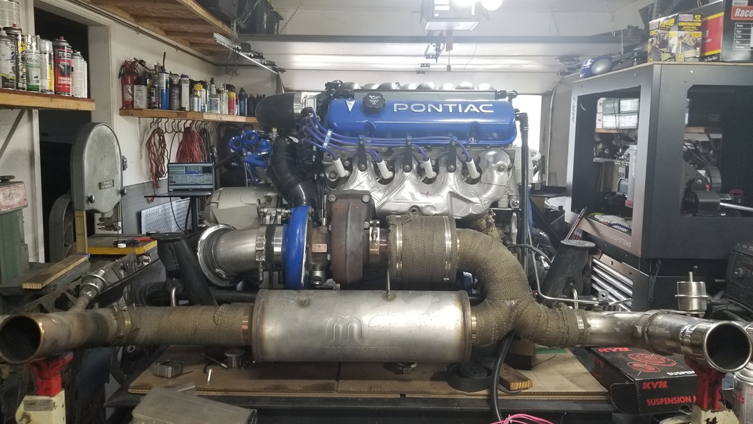
Here is a picture of the layout.
quote
Originally posted by dskebo:
I ran a pcv setup like that and it sucked the oil out of the engine so fast I almost damaged it.
While your setup might have done this, I don't have any concerns.
I forgot to post a picture of the panel that will be in the old radio area. It will be painted black.
Mechanically, the engine is just about ready to go back in the car. Maybe another hour to finish a few odds and ends:
The engine to ecm harness is pretty much complete. Most of the rest of the wires connect to the C203, C500, or other items in the car, so electrically it is just about ready for install.
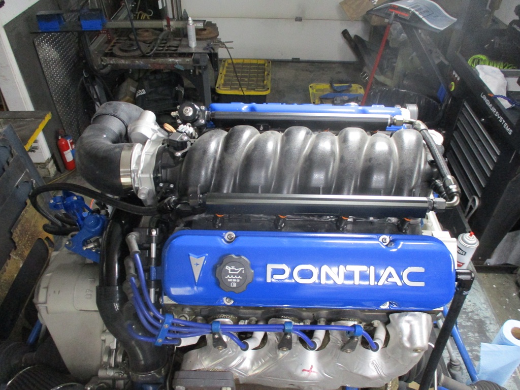
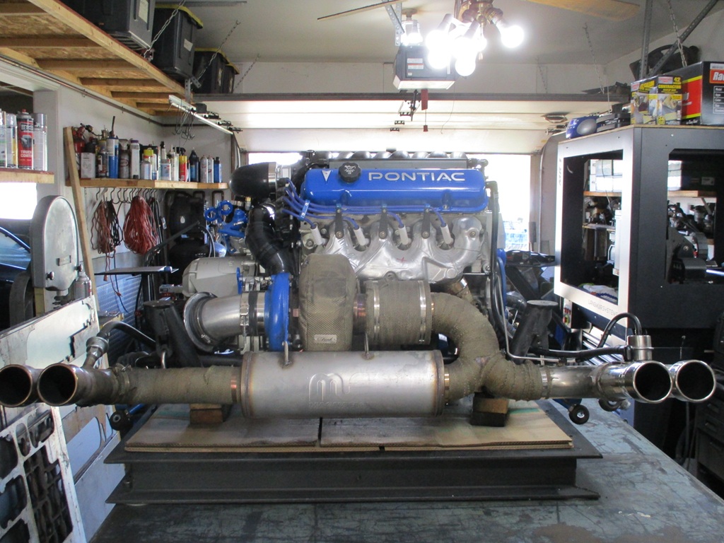
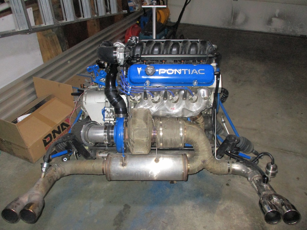
Last few pictures of the drivetrain on the work table:
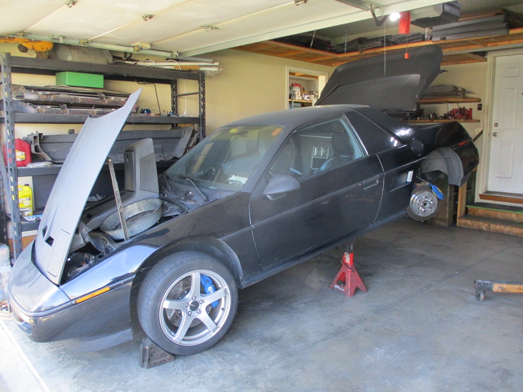
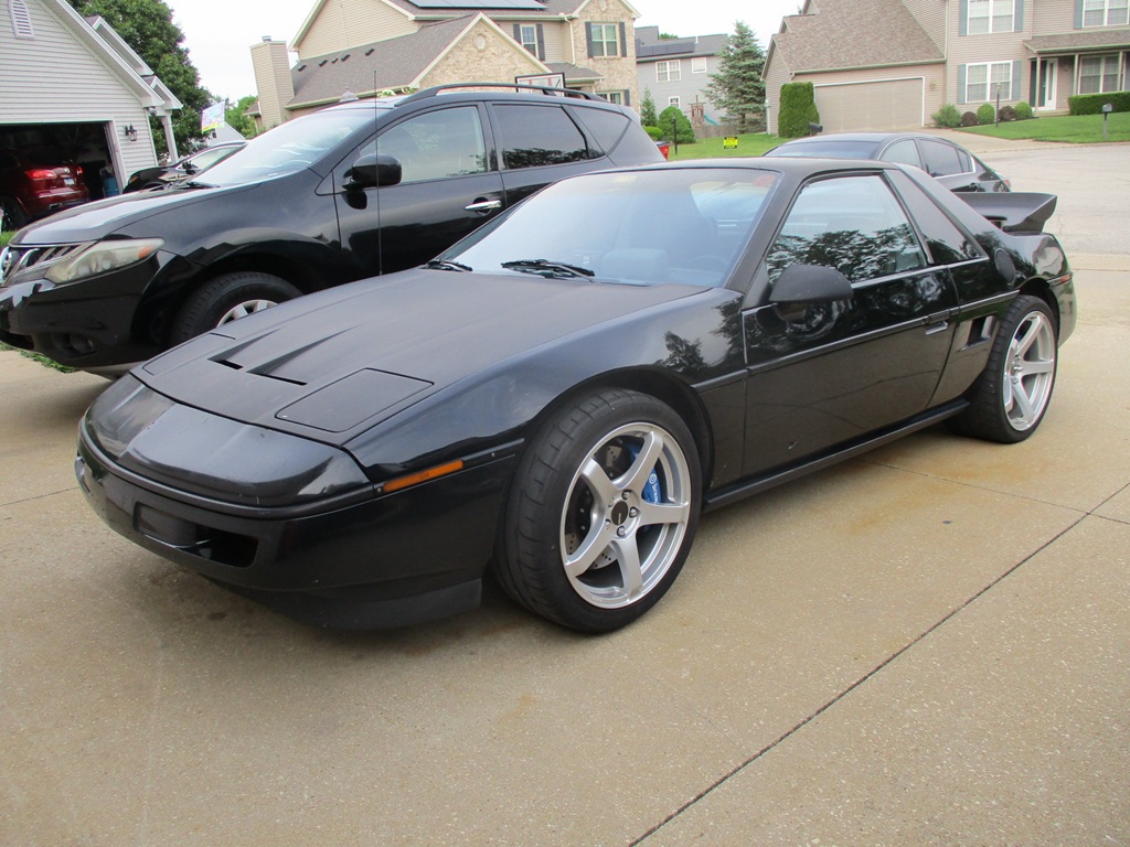
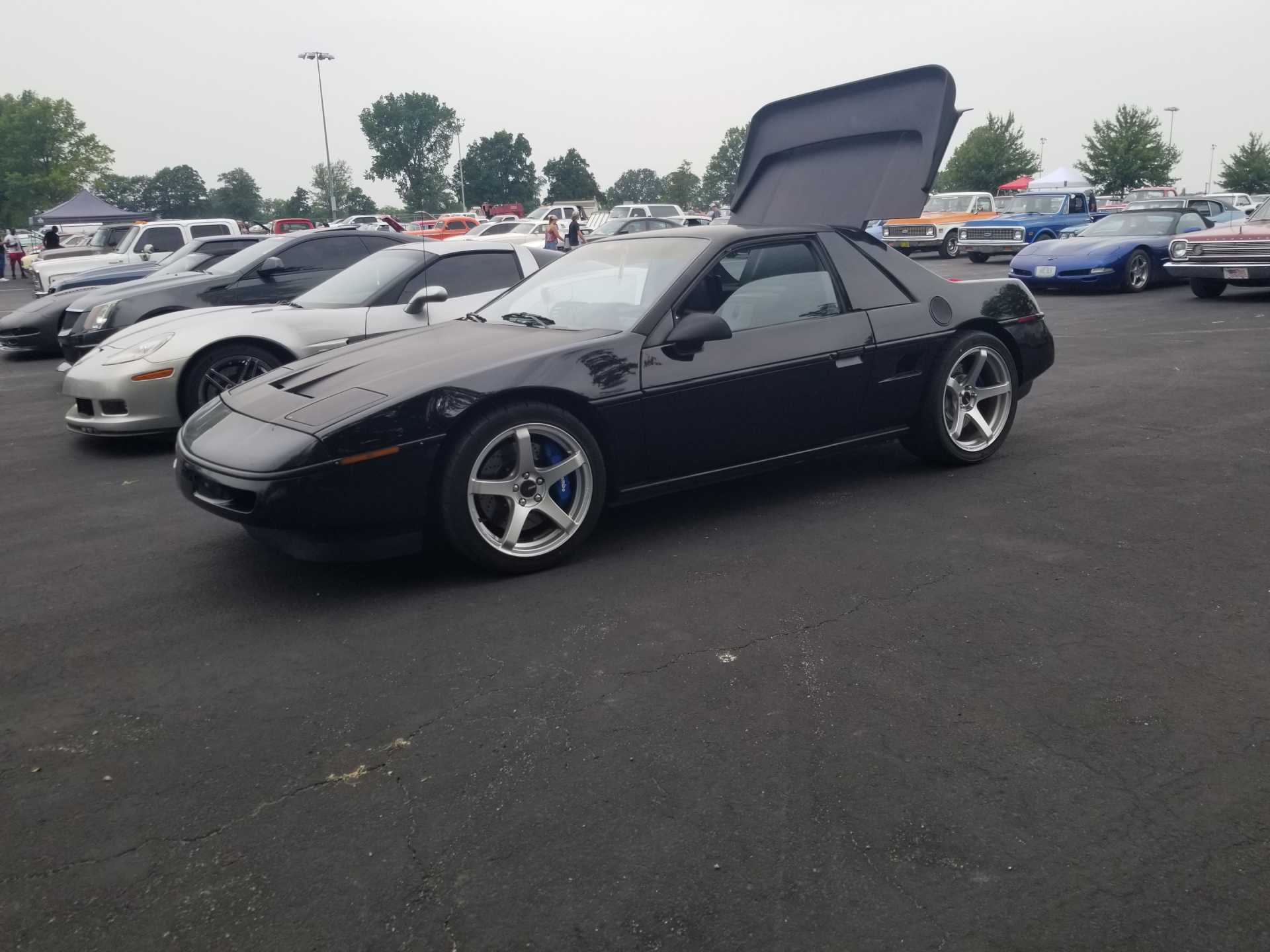
Fiero ready to receive the drivetrain.
Drivetrain now in Fiero bay. It is off the legs of the cherry picker because the Fiero was raised 1" too little, so I had to remove the drivetrain from the cherry picker. Use the cherry picker to raise the Fiero another 1" and then go back and pick up the drivetrain again.
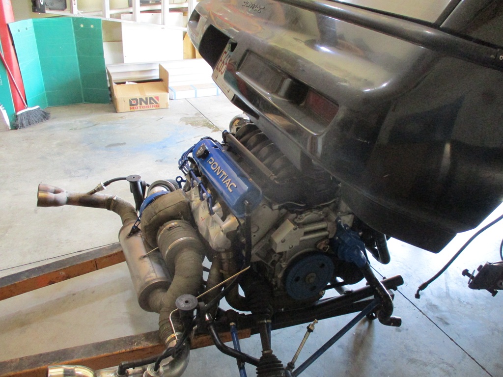
Drivetrain going under the Fiero:
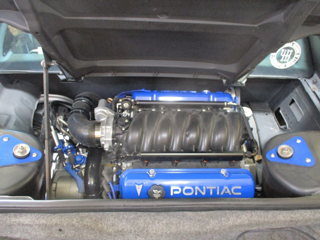
Cradle all bolted up:
I knew I hadn't test fitted the new tensioner placement, but everything was good in the drawing... ends up the firewall is about 0.400" closer, which means the belt just barely rubs.
With a thin M8 washer and remaking the tensioner bracket, I can rotate the tensioner about 4 degrees from the firewall and gain about 0.140" clearance for starters. I will look for a slightly smaller pulley to help with the clearance, then upsize one of the other ones to keep the belt length the same.
I plan to work on finishing the critical connections this week after work and targeting next weekend for the test start.
[This message has been edited by fieroguru (edited 04-27-2025).]
I know its too late now BUT a few casters bolted to the bottom of the wooden stand you had the subframe on makes it SO much easier to roll it under the car.
I know its too late now BUT a few casters bolted to the bottom of the wooden stand you had the subframe on makes it SO much easier to roll it under the car.
I built exactly such a dolly for moving my cradle around. The bottom of the cradle ends up 3" above the floor, so it does not require much extra lift of the body.
I know its too late now BUT a few casters bolted to the bottom of the wooden stand you had the subframe on makes it SO much easier to roll it under the car.
I don't have a wooden stand for the drivetrain to sit on, just random blocks of wood when needed.
The cherry picker legs work and I don't need to store another dolly or cart. I am very space challenged.
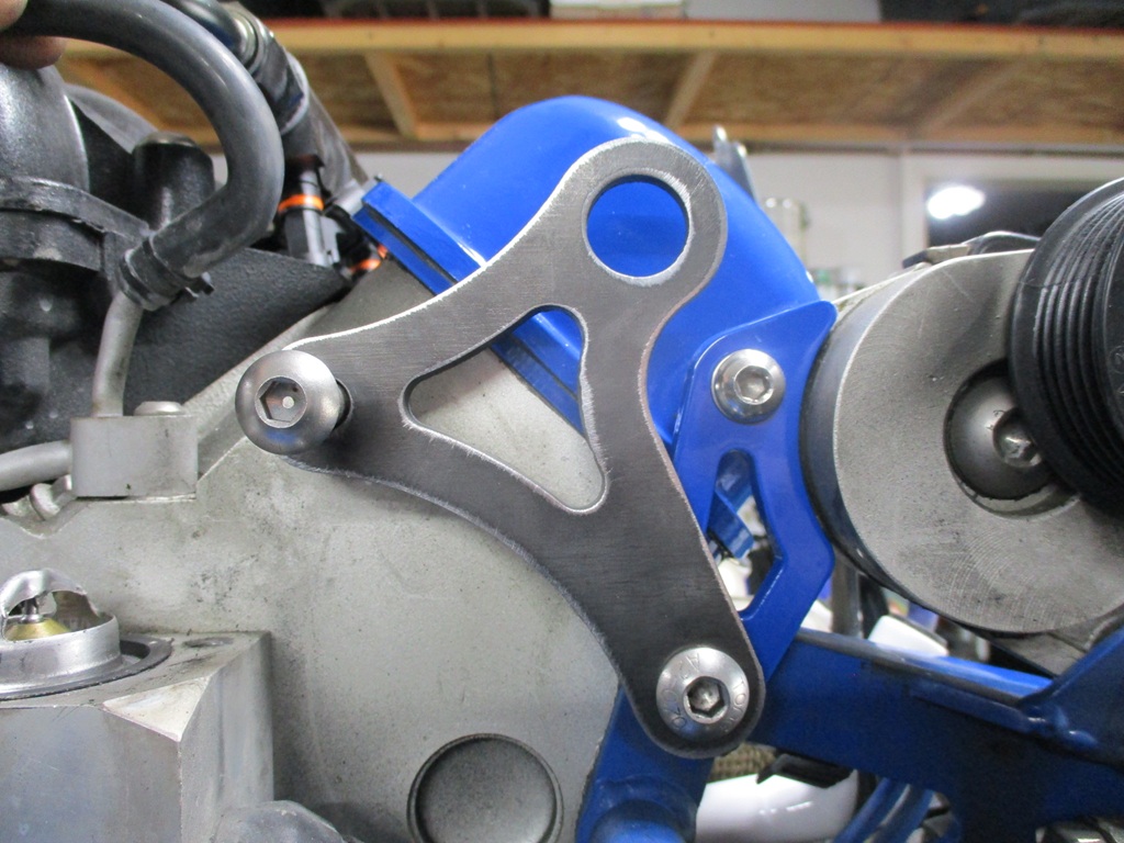
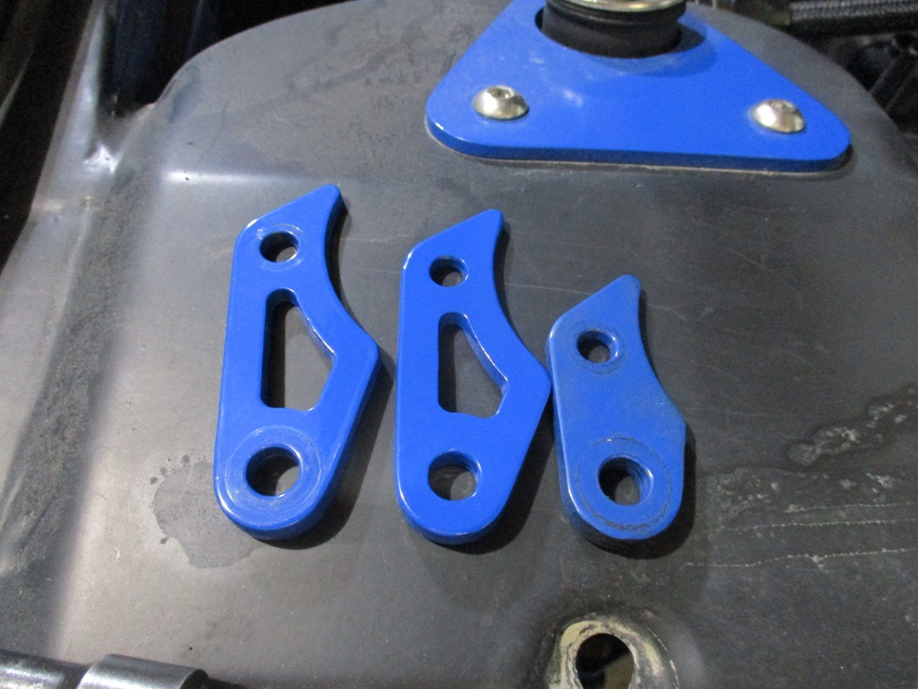
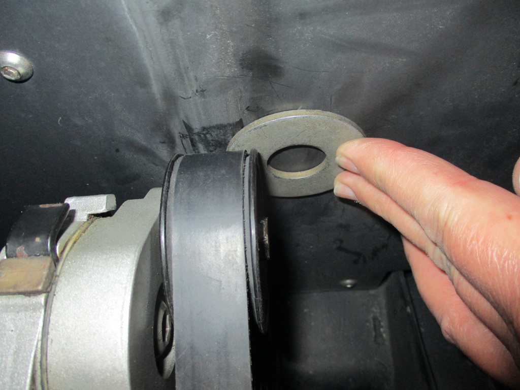
I am starting to get a collection of these tensioner brackets:
The middle one allows the valve covers to fit with the least amount of rotation of the tensioner:
With this being the only change, there is now 0.14" clearance as shown with the washer:
I will likely upsize one of the other idlers to restore the lost tension from lowering the tensioner, and when doing that the clearance will increase to about 1/4" which will be more than enough.
The cause of the clearance issue is when I made the drawing, it was on a parts chassis which does not have the smooth firewall panel spaced from the oem firewall.
Made some more progress, but didn't get as far as I would have liked.
During this past week:
I setup the base tune in the Haltech ECM and configured the I/O for all the extras (Boost Control, Flex Fuel, Traction Control, Speedo, A/C, Cruise, Clutch Switch)
Fuel return hose installed.
Shifter cables installed.
Clutch Line Connector is hooked up - but clutch is not bled.
Brake booster vacuum line connected and insulated (close to the wrapped and heat shielded front manifold).
Heater hose connected.
+12V Battery cable to starter connected.
Fuel supply hoses connected at filter & flex fuel sensor.
Axles are in the wheel bearings & trailing links & sway bar links are attached to the struts - but not tighened. Still need to connect the lateral links and tighen everything up.
Things that needed some reworking and took a fair amount of time:
1. Heater hose connection. When I pulled the drivetrain in the fall, I forgot to disconnect this line and ended up bending the 5/8" aluminum tube past the OEM quick disconnect. So I ended up cutting the aluminum tube to remove the kink, then made a reducer to the 3/8" hose from the engine.
2. Driver side coolant hose. Since I reworked the coolant crossover tube to maximize space for an intercooler, I needed to made a new one. Of course I was one heat shrink tube shy, so I had to run across town to pickup another one. With this new hose, I was able to install both coolant hoses from the cradle to the chassis.
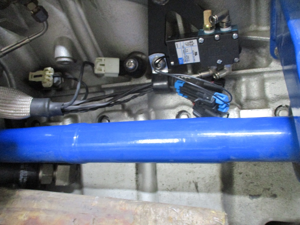
3. - Battery cable and alternator ground straps. The - battery cable was too long, so I cut it to a better length and installed a new cable end. Went ahead and made a new chassis to engine ground as well. While making these, I got to try out a new tool I picked up last year.
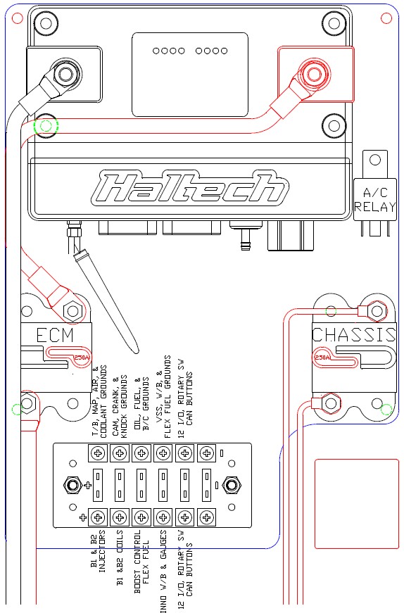
4. Made the +12V cable from breaker to ecm. Here you can see the cable end crimp:
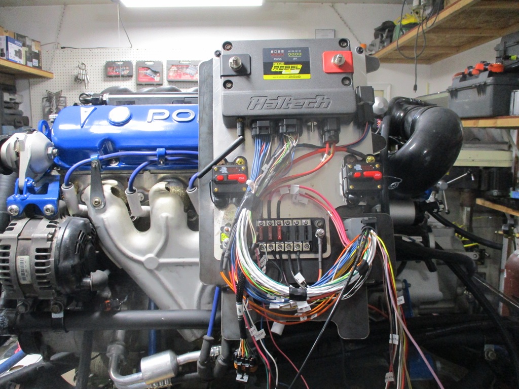
5. Installing the ecm panel, breakers, and fuse panel and connecting them:
I still need to:
Remove some old wiring in the console area to the pedal and gauges,
Make the connections to the 203C and 500C connectors,
Install the Haltech sub harness to the pedal
Run the 4ga wires from the Haltech ecm to the front battery - after this point, I will try to start the engine!
Run wires for the Haltech 12 position rotary switch and the 12 I/O expansion module forward to the HVAC area,
Rewire the Innovate W/B and A/F gauge
Rewire the aftermarket instrument gauges
[This message has been edited by fieroguru (edited 05-04-2025).]
It was a busy week, but I managed to get all the critical wiring done and the car started on Saturday.
Sunday I put the rear suspension together, aligned the car, swapped out the radiator fan (bad bearings), and played around with the Halrch NSP tables. While the car started with the base information and tables, the values and units were not what I was used to. So Saturday night I did a lot of playing with the software and changed the Target A/F, VE, LTFT, Timing & Knock long term trim to all have the same axis, units, and rows and columns. I also spent some time converting the timing table I had with the E40 grams/cly vs RPM to MAP ve RPM to get the timing closer than the supplied table.
This ecm is closed loop wideband from idle to WOT and through boost. So there is a table where you can specify the target AFR for each individual cell. Here is what my rough AFR target table looks like. Some of the targets are a little rich for dialing them in and will be leaned out as the tune takes shape. I will likely flip axis so 400 RPM and 35 KPA is in the upper left, again to match what I am used to.
The NSP is tuner and logger in one. The long term trims tables for knock and fueling auto populate based on what corrections the ecm is doing, then they both have a buttom to apply the changes to the base MAP. So that is super easy. The long term trims for fuel and knock are capped at 16x16 tables, but the actual VE and Timing tables can go to 32x32. It is super easy to add columns and rows and the software autopopulates them with values (midpoint of the adjacent cells. Once I have the VE and Igntion tables roughed in, I will likely expand them to 32x32 and restrict the long term trims to 1/4 of the table at a time so I can have 100 to 150 rpm resolution for the cells for interstate speeds and lean the mixture out in my quest for 30 mpg.
A couple of cool things that should help a bunch before I get some of the other higher level features enabled (traction control and boost by gear).
Throttle body opening limit @ zero speed - It can be set from 0-40%. I think this could be used as a simple agressive launch mode. Where I floor the pedal, engine holds x% throttle and x RPM (probably 3500 or so RPM), until I release the clutch.
Gear identification - based on rpm and VSS settings the car will know what gear it is in once the clutch is engaged.
Pedal to TB tuning by gear - this will allow me to limit the throttle body opening % in 1st and 2nd gears to smoothly reduce power and launch the car w/o wheel spin. Gaining much more forward motion and speed in the two lowest gears where the car was already over powered before the turbo. This partial throttle opening will also help avoid boost until later in 2nd gear. 3rd gear has proven to be able to hold boost, so it will be 100% throttle and full boost.
This is a very feature packed software, that seems to only be limited by Inputs/Outputs, but Haltech has expansion modules for more I/O. Here are all the available features that can be turned On/Of:
I still need to:
Run wires for the Haltech 12 position rotary switch, 12 I/O expansion module, and the CAN buttons forward to the HVAC area,
Rewire the Innovate W/B and A/F gauge
Rewire the aftermarket instrument gauges
Rewire the aftermarket instrument gauges
Hook the stereo back up so I can have tunes while driving
Install the missing interior panels
Cut & crip the A/C lines
Charge the A/C
RUn front wheel speed sensor to the I/O module
Wire clutch & brake predal switches to I/O module
Create cruise hareness from pedals, and stalk to I/O module
Originally posted by fieroguru: Throttle body opening limit @ zero speed - It can be set from 0-40%. I think this could be used as a simple agressive launch mode. Where I floor the pedal, engine holds x% throttle and x RPM (probably 3500 or so RPM), until I release the clutch.
I did something like this with the stock 2.8, but I didn't need to use a clutch pedal switch.
Once the tires started rotating (well, the VSS registering movement), that was enough to leave the launch mode and goto normal operation.
Ran and drove the car about 6 hours on Saturday. It will idle for an hour in the driveway without temps going over 200 degrees. Was able to get starting, idling, and part throttle tuning roughed in.
Still need to spend some time going through some old data logs when it was E67 and E40 to double check the timing in the part throttle/interstate cruise areas.
Working on fixing an oil leak currently, planning to have that fixed on by Wednesday, then will put the rest of the interior back.
It was really nice to be driving the car again with it's stereo and my tunes! I have missed it!
I would like to put 500 to 1000 miles on the swap before the 30th.
Originally posted by Trinten: Curiously... the 30th... what? HP Tour?
Vince, I am taking some time off starting the 30th, and then the HRPT starts on June 9th. I am registered as a Long Hauler.
Another good weekend of progress.
A/C hoses made, vacuumed the system for several hours, it held vacuum for several hours, so I charged it up and it works great!
I finally have nearly all the wiring done. Just need to terminate the 2 wires for the front wheel speed sensor.
I got the CAN network going with the 12 I/O expansion module and the 2 x 4 CAN buttons operational.
The speedo was fighting me for a couple of days. The earlier concern about the VSS tooth count being maxed at 50 vs. it needing to be 68 for the 3.091 is a non-issue. There is another way to input the needed numbers. The Rebel LS does not have a speedo output, but I was able to configure a generic output to drive the speedo. Now the GPS, ECM, and Speedo all read 80 mph at the same time.
Importing the timing from the E40 was a nice improvement.
I did waste about 2 hours chassing a self-inflicted issue. Gettng the CAN network operational left the car unable to go above 10 mph. It would just fall on its face and the A/F ratio would go to 21.x... After loading some prior tunes and checking fueling and timing, it did not going away. Then I realized it was traction control working like it is supposed to. With the front wheel speed sensor disconnected, but traction control turned ON (It is one of the 2x4 CAN buttons and I set it to default to ON so I have to turn it OFF). Well it came ON as soon as the CAN network was enabled and the missing front wheel speed sensor triggered the injectors to start shutting off. Disabling the traction control feature fixed the issue.
I drove the car for about 60 miles today. Have to go to downtown Chicago on Tuesday, but not ready to take the Fiero. Wednesday, Thursday, and Friday I will daily drive the Fiero to work. After work I will drive it some more and one night I will do a 150+ mile interstate run to check MPG.
Glad you figured out the speed settings to get it to work, are you using the F40 VSS or the wheel average from the wheel speed sensors?. Have you been looking into converting completely to a digital dash setup? Hopefully you are also taking advantage of the closed loop boost control.
I have been slowly working on my own CAN to Fiero Gauge cluster driver, which I plan to start with the Haltech CAN, Holley CAN and MSII CAN. It would help free up I/O on the ECU for other controls.
Currently using the stock Fiero speedo and tach, but wouldn't mind a 8K tach and a 160 speedo. Had digital gauges in my 86 vette 20+ years ago and much prefer the dial gauges.
I will be playing with boost control later this summer.